 Introduction to
Naval Weapons Engineering
Introduction to
Naval Weapons EngineeringSonar Propagation
By virtue of the fact that the speed that acoustic waves
travel at depends on the properties of the medium (i.e. sea water),
the propagation of sonar will be complicated. So complicated
in fact that it will be impossible to accurately predict without
the use of a computer model. However, sonar systems rely heavily
on operator input and control to maximize their performance.
Many of the decisions made regarding the maneuvering of the ship
carrying the sonar system will also affect the sonar's performance.
Therefore a detailed knowledge of the salient features of sonar
propagation is essential to its successful employment. We begin
with a simple model for the transmission loss.
Transmission Loss Formula
Transmission loss (TL) can be predicted, to a very rough
degree, solely on the basis of a few factors. These factors are
range, and frequency.
Range Effect
The simplest case, which is the identical case used in
electro-optics and radar, is to assume all of the acoustic energy
is uniformly distributed in all directions. In sonar this is
termed spherical spreading loss, since the intensity will
fall off proportional to the surface area of a sphere.
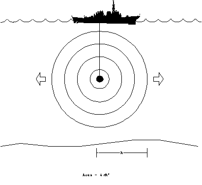 Figure 1. Spherical spreading.
Since the area over which the energy is distributed at range,
R, is 4pR2, the ratio of
any two intensity levels at different ranges can be computed.
If we take the decibel equivalent, and take the first range as
one meter, which happens to be where the source level is defined,
we obtain the spherical spreading loss f part of TL:
TLspherical = -10 Log { I(R)/I(1 m)} = -10 Log{1/R2}
TLspherical = 20 Log(R) .
The negative sign was included since TL is defined to be positive
quantity, and is subtracted in the SNR equations.
When the acoustic energy reaches either the surface or
the bottom of the ocean, it is generally reflected back. A long
range, all of the acoustic energy will tend to confined between
two planes, one at the surface and the other at the bottom. Therefore,
the energy can no longer spread out like the spherical spreading
case, but now becomes cylindrical spreading.
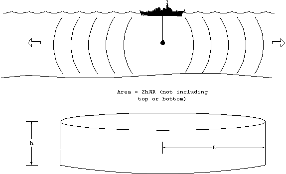
Figure 2. Cylindrical spreading.
The area over which the energy is distributed now varies directly
with range, R. The common factors will cancel, and the transmission
loss between two ranges will be 10 Log( R). Explicitly this means
SPL(R2) = SPL(R1) - 10 Log(R2/R1).
It would be nice if we could choose R1 to be one meter
in which case SPL(R1) = SL, but this would be incorrect.
That would be akin to claiming that the spreading losses where
cylindrical starting from one meter. Clearly, in regions where
the water depth is larger than the range, the spreading must be
spherical.
The question now becomes: at what range does the spreading
loss transition between the spherical and cylindrical case.
If the source where located exactly in the middle (halfway between
the surface and bottom), then it seems plausible to make the transition
when the range is one-half the water depth since this is when
the surface of the sphere will just touch the bottom and top.
The transition range will depend on the location of the source
and the depth of water. For purposes we assume the transition
range to be 1000 m, since the average ocean depth is about 2000
m.
At 1000 m, the transmission loss due solely to spherical
spreading will be 60 dB. Taking this as the starting point for
cylindrical spreading, we can patch the two equations together
by adding 30 dB to the 10 Log(R) spreading. This is proven below:
TLspherical(at 1000 m) = 20 Log (1000) = 60 dB
TLcylindrical(at 1000m) = 10 Log(1000) = 30 dB
If we wish to apply the TLcylindrical formula starting
at 1 m, then we must add the difference at 1000m, therefore
TLcylindrical (R) = 10 Log(R) + 30 dB. (valid when
R > 1000 m)
At ranges of less than 1000 m, you must use the spreading
spreading loss formula, TLspherical = 20 Log(R).
absorption/scattering
Like air in electro-optics, the intervening water between
the source and receiver will either absorb some of the acoustic
energy passing through it. The dependence on range will be identical
to Bougher's law, but now in decibel form:
Tlabs = - 10 Log( e-bR)
= (10 b)R
where b is the extinction coefficient.
The factor of 10 and a unit conversion into km is absorbed in
the definition of the absorption coefficient, a
b/100, therefore
Tlabs = a R.
where a has units of dB/km. The absorption
coefficient has a strong frequency dependence, meaning much greater
losses at higher frequency. The absorption coefficient can be
calculated from a formula:
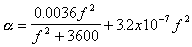
where f is in kHz, and the result for a is in dB/km.
or using a graph:
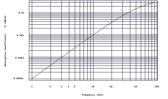 Figure 3. Absorption coefficient
as a function of frequency.
Other losses
Many other things can happen to the acoustic wave as it
propagates. For example the energy may scatter off particles
or biologics. Energy will be lost upon reflection from the surface
and bottom. And lastly, by but far the greatest factor of all
will be the change in the propagation due to the variations in
the speed with temperature, depth and salinity. The change in
speed will tend to distort the perfect spherical or cylindrical
shape of the wave front. This does not, however, always result
in greater transmission losses. As we shall soon see, there are
many conditions which tend to concentrate acoustic energy resulting
in a lower than expected transmission loss.
All of these factors just discussed can be lumped into
a single term, A, called the transmission loss anomaly.
This is surely artificial and is only used in order to be able
to write a complete equation for TL. All deviations from the
predicted result can be explained away in the term A. The equation
so written is
TL = 10 Log(R) + 30 + aR + A
If you ignore, the last two terms, the range dependence
is very straight forward, and can be used to generate some rules
of thumb:
TL 60 dB at 1 km
TL 70 dB at 10 km
TL 80 dB at 100 km.
This is based on nothing but the spherical and cylindrical spreading
losses, assuming the source is exactly in the middle of 2000 m
deep water. What one finds in practice, are variations about
these baseline numbers. This can also be shown in graphical form,
TL vs. range.
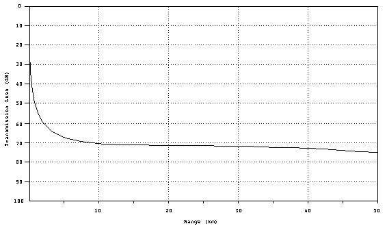
Figure 4. Geometrical
transmission loss curve.
Propagation Paths
To gain further insight into how the environment can affect
propagation, we first study how the propagation speed varies in
the ocean.
The Sound Velocity Profile (SVP)
The largest variation is the speed of sound in water occurs
with changes is depth. Obviously the pressure increases with
depth causing a uniform increase of +1.7 m/s for every 100 m.
Furthermore, the ambient temperature changes with depth. A
plot of propagation speed (velocity) as a function of depth, is
called the sound velocity profile (SVP), and it is the
fundamental tool for predicting how sound will travel. Neglecting
salinity, the SVP can be obtained from sampling the ambient temperature
at various depths (the pressure contribution never varies). An
inexpensive probe to do this is called an expendable bathythermograph
(XBT). The resulting SVP looks like this:
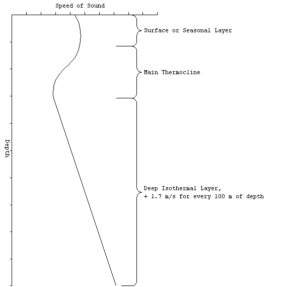
Figure 5. Oean layers.
The SVP reveals some common structure to the ocean. The water
can be divided into three vertical regions.
The surface (seasonal) layer is at the top and is the most variable
part. As the name suggests, the profile will changes depending
on the time of day (diurnal variation) and the season (seasonal
variation). During the day, the heat from the sun (insolation)
causes the water at the very top to be warmer than the water below.
Since the condition of warm over cold is stable, the condition
is quite common. Late in the afternoon, particularly on a bright
day, the surface temperture will be the greatest and so one would
expect the greatest gradient (change with depth).
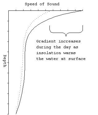 Figure 6. Diurnal variation in
SVP.
The main thermocline connects the seasonal layer with the uniformly
cold water found deep in the ocean. Below about 500 m, all of
the world's oceans are at about 34o F. The positive
gradient in the deep isothermal region is solely due to the pressure
effect.
In the summer, the seasonal layer tends to have a strongly
negative gradient, for the same reason as given to explain the
diurnal variation. So the summer profile looks like:
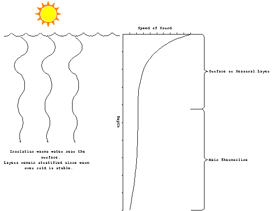
Figure 7. Summer SVP.
In winter, the water is generally warmer than the air. A lot
of heat is lost through advection and radiation. However, one
would not expect to see cold water setting on top of warm water
for very long. Convection brings the warm water to the surface
destroying the effect. The surface layer tends to be closer to
isothermal than anything else. Additionally, strong winter storms
and their large waves frequently mix the surface layer to a depth
of up to 100 m. For the nearly isothermal surface layer, one
could expect a weakly positive gradient above the main thermocline.
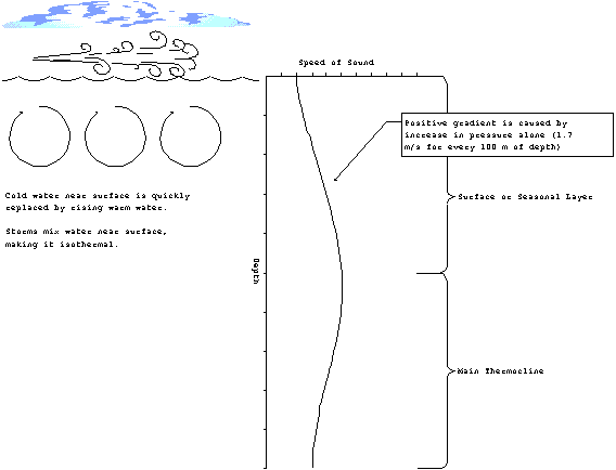
Figure 8. Winter SVP.
Ray Tracing
The change of propagation speed with depth will manifest
itself through refraction of the sound. A graphical method of
illustrating the effects is called ray tracing. The basic idea
is to draw lines perpendicular to the wave fronts and follow their
paths. For a typical sonar array, these lines start equally spaced
within the beam capability of the array (discussed in the next
chapter).
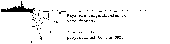
Figure 9. Ray tracing.
As the rays go deeper, they begin to refract. Recall how differences
in the index of refraction (which are a measure of the propagation
speed) affected electromagnetic waves. As the rays move into
a medium which has a slower propagation speed, they tend to become
more vertical. On the whole, the rays will deflect downward in
a negative gradient.
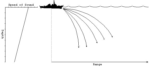
Figure 10. Negative SVP
gradient.
As you might expect, the opposite effect occurs when the gradient
is positive. As the rays enter deeper water the propagation speed
increases and the rays bend upwards.
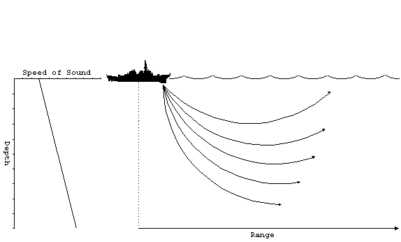 Figure 11. Positive SVP gradient.
All of the rays will be deflected upwards. When the rays reach
the surface, the will be reflected back downwards and the same
process begins again. Naturally, some of the energy is lost and
the reflection, but the overall effect is to trap the sound in
a relatively small layer below the surface. The sound does not
reach the deeper regions, so the transmission less than you would
expect for cylindrical spreading. This effect is called a surface
duct.

Figure 12. Surface duct.
The other common propagation modes occur during combinations of
positive and negative gradients. A positive gradient over a negative
gradient produces a special kind of propagation, where the rays
split at the boundary which is called the layer. The depth
of maximum sound velocity which ocurs on the layer is called the
layer depth (LD).
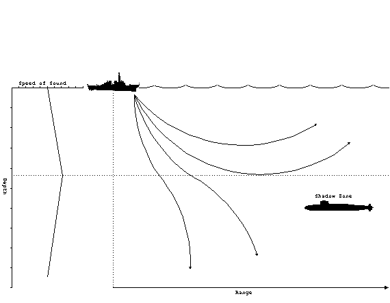
Figure 13. Sonic layer.
Above the layer, the positive gradient will produce a
surface duct as previously described. When rays penetrate below
the layer, they are deflected downward. Therefore, the rays diverge
above and below the layer. Beyond a certain minimum range, the
rays from the source will never reach locations just below the
layer. This is called the shadow zone. It is a favored
depth for submarines to operate at for just this very reason.
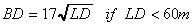
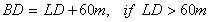
The optimum depth to operate at, called best depth (BD), is a
function of the layer depth. The best depth can be calculated
from
For the case where the negative gradient is over the positive,
rays which originate at the boundary will be deflected back towards
the middle, regardless if they go up or down. This forms a sound
channel, where the rays are then confined to the small region
above and below the axis, called the sound channel axis.
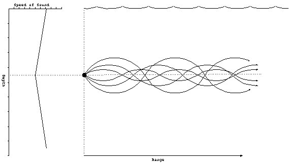
Figure 14. Sound channel.
The sound channel will not work for rays that begin at the surface,
like in the other cases. The source must be located near the
axis. Several sonar systems have features which allow them to
be placed near the sound channel axis. For example, sonobouys,
which are small self-contained sonar systems, have a setting
which places them at a typical sound channel axis depth.
Another special type of propagation occurs when the water
is so deep that no sound can reach the bottom without being deflected
upwards by the normal positive gradient found in the deep isothermal
layer. This situation requires a minimum of 200 m of depth
excess which is defined as
depth excess: the distance from the lower boundary of the sound
channel to the bottom.
When all of the sound rays are returned to near the surface, they
tend to converge into a small region. Therefore the sound pressure
level is increased dramatically in this region known as a convergence
zones (CZ).
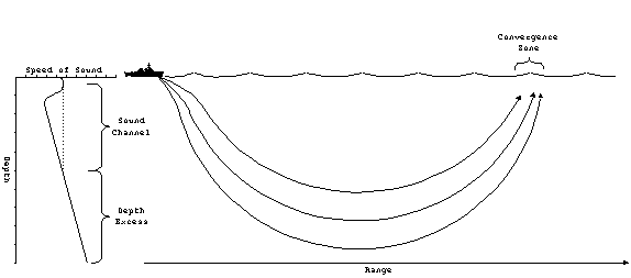
Figure 15. Convergence
zone.
The convergence zone tends to be at large distances, typically
20-30 nm from the source. It is possible to have multiple convergence
zones, which will occur at regular intervals. For example, if
the first CZ is at 30 nm, the second CZ would be at 60 nm. The
CZ is only a few miles wide, and therefore, contacts which are
acquired through convergence zones tend to appear and disappear
quickly.
It may be possible for a ship to have a rather limited
sonar range due to regular transmission losses but multiple convergence
zones. These zones form protective rings about the ship. A hostile
submarine closing in on the ship would be detected as it passes
through the various convergence zones, thereby alerting the ship
to its presence. The ship could then deploy mobile ASW assets
like a helicopter to handle the submarine.
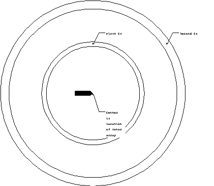 Figure 16. Annulus of CZ.
Finally the last type of propagation occurs in when the sound
is strongly reflected from the ocean floor. The rays tends to
converge near the surface, resulting in a reduced transmission
loss. This is called bottom bounce propagation. Rays
from bottom bounce can be identified from the others because of
the larger angle of incidence. Typical bottom bound comes into
the sonar at angles of more than 30o from horizontal.
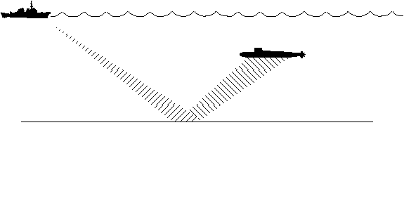
Figure 17. Bottom bounce.
Only certain ocean floor conditions are conducive to bottom bounce
propagation. Flat and hard ocean floors tend to be the best.
Soft mud, on the other hand is the worst.
Figure of Merit
Because the propagation of acoustics waves in the ocean
is fairly complicated, the use of a formula for transmission loss
is of limited accuracy. Computer models can be used to produce
much more accurate plots of TL as a function of range, known as
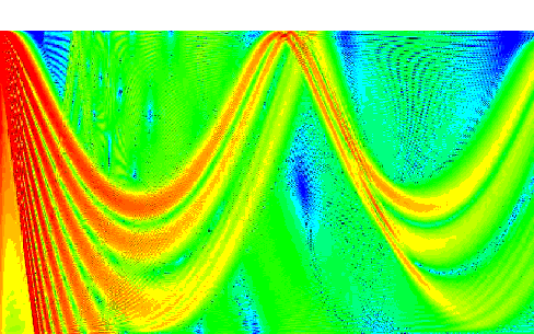
transmission loss curves. Here is a typical TL curve showing
some of the features just discussed:
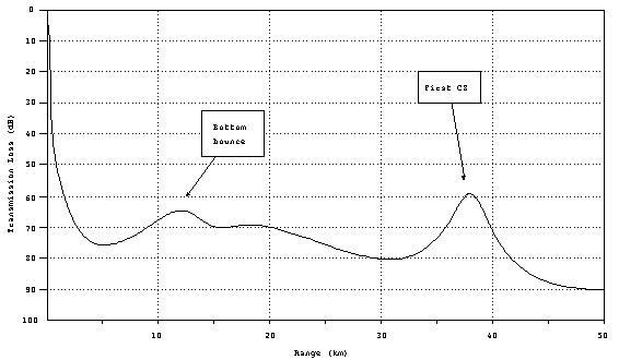
Figure 18. Typical TL
curve.
In comparision to the geometrical TL (spherical and cylindrical
spreading losses) you will note there are certain ranges where
the TL actually goes down with increased range. These are locations
where the refraction effects of the ocean cause the sound rays
to concentrate. This example illustrates the effect of bottom
bound and CZ.
Given an accurate transmission loss curve, we are now
in a position to estimate the maximum detection range of a sonar
system. Recall that detection is possible whenever
SNR < DT.
To solve for range, we only need rearrange terms to isolate
the range dependence. For the passive case, define figure of
merit, FOM
FOMpassive SL + DI - NL - DT
Now the detection criterion becomes
FOM > TL.
Which leads to the following interpretation:
Figure of Merit (FOM) is the maximum transmission loss the system
can have and still be able to detect the target (at 50% of the
time).
If FOM is known, then the maximum range can be determined
by plotting the FOM as a horizontal line on the TL curve. All
ranges where the FOM > TL (remember that TL is increasing in
the down direction), are detectable.
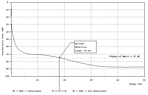
Figure 19. Determining
maximum detection range from FOM.
In this example, the FOM = 75 dB. From the graph, it is apparent
that FOM > TL everywhere less than 18 km, which is the maximum
detection range.
FOMactive SL + TS + DI - NL - DT
For active systems, there are (at least) two complications.
First the FOM is modified so that
Secondly, the transmission loss is incurred twice, as the sound
travels to the target and back. You could use a separate curve
with twice the TL vs. range, or alternatively, use one-half the
FOM, which is the preferred method. So for active systems, the
detection criterion is:
FOM > 2 TL or FOM/2 > TL.
Therefore, you calculate FOM and then plot FOM/2 on the TL curve
to obtain range in the same manner.