ASSIGNMENT SHEET
INTERNAL COMBUSTION ENGINE THEORY and CONSTRUCTION
Assignment Sheet Number 60B-103
INTRODUCTION
The basic diesel, or internal combustion engine is a heat engine. Chemical energy is changed to mechanical energy inside a cylinder. In other types of heat engines (i.e. Boilers), energy developed by fuel is first transferred to steam, and the energy in the steam is converted to work (in the turbines) which is farther transformed into shaft energy to be utilized to turn generators, reduction gears, and other equipment.
LESSON TOPIC LEARNING OBJECTIVES
Terminal objective:
6.0 DESCRIBE the principles, construction, function, components, control and monitoring systems, and operation of a diesel propulsion plant and associated auxiliary support systems. (JTI:A)
Enabling objectives:
6.1 COMPARE and CONTRAST a gasoline engine with a diesel engine.
6.2 DEFINE the following terms as applied to diesel engines:
a. Compression ignition
b. Compression ratio
c. Cycle
d. Displacement
e. Four-stroke cycle
f. Horsepower (hp)
g. IDC/ODC (opposed piston engine)
h. Internal combustion
i. Jacking
j. RPM
k. Stroke
l. TDC/BDC
m. Timing
n. Two-stroke cycle
o. Valve lash
6.3 DEFINE the following terms used with Diesel Engine Air System:
a. Exhaust stroke
b. Intake stroke
c. Naturally aspirated
d. Scavenging
e. Supercharging
f. Turbocharging
6.4 DEFINE the following terms used with Diesel Engine Lubricating and Cooling Systems:
a. Cooler (heat exchanger)
b. Pressure
c. Pressure differential
d. Thermal expansion
e. Water jacket
f. Viscosity
g. Coolant treatment
6.5 DEFINE the following terms used with Diesel Engine Fuel Systems:
a. Atomization
b. Combustion
c. Detonation
d. Fuel knock (diesel knock)
e. Fuel injection
f. Ignition lag (delay)
g. Precombustion
h. Priming
i. Turbulence
6.6 STATE the functions of each of the following primary parts/assemblies of a diesel engine:
a. Accessory drive assembly
b. Block
c. Camshaft
d. Connecting rod
e. Crankcase
f. Crankshaft bearings
g. Crankshaft
h. Cylinder head
i. Cylinder liners
j. Drive mechanism
k. Manifold (intake/exhaust)
l. Piston
m. Sump/oil pan
n. Valves (intake/exhaust)
o. Flywheel
p. Thrustbearings
q. Inspection covers
r. Explosion covers
s. Connecting rod bearings
t. Piston/wrist ring
u. Piston rings
v. Camshaft bearings
w. Attached pumps
x. Fuel injectors
y. Turbocharger
z. Fuel rack
aa. Crankcase exhauster
ab. Fork and Blade
ac. Push rods
ad. Push rod lifters
ae. Rocker arms
af. Vibration dampers
ag. Barring gear
ah. Balance shafts
ai. Drive gears
aj. Idler gears
6.7 STATE the different classifications of diesel engines according to the following:
a. Mechanical cycle
b. Cylinder arrangement
c. Combustion action
d. Cooling media
e. Valve arrangement
6.8 DISCUSS the pressure, temperature and volume relationship of the gas flow through a diesel engine cylinder for the following events:
a. Scavenging
b. Compression
c. Combustion
d. Expansion
e. Exhaust
6.9 UNASSIGNED; reserved for future use.
6.10 UNASSIGNED; reserved for future use.
6.11 UNASSIGNED; reserved for future use.
STUDY ASSIGNMENT
1. Read Information Sheet 60B-103.
2. Outline Information Sheet 60B-103 using the enabling objectives for lesson 60B-103 as guide.
3. Answer study scenarios.
STUDY SCENARIOS
1. You are walking through the main machinery space and you notice EN3 Foster studying for the next advancement exam. EN3 Foster tells you that he/she is having trouble understanding the phases of the four and two stroke engines. How would you help explain to EN3 Foster the phases of the four and two stroke engines?
2. Once you have finished explaining the 4/2 stroke cycles to EN3 Foster, EN1 Edwards asks you how to classify diesel engines. Explain to the EN1 how to classify a diesel engine.
3. You are walking on deck when you hear ENFN Jones tell BMSN Smith that there is no difference between a turbocharged engine and one that uses a blower. Is this correct? How would you explain the differences to both of them, if there is a difference.
4. ENFN Myers is having a hard time explaining to ENFN Booth the definition of supercharging and what is does for an engine. Myers turns to you and asks you to explain supercharging to both of them. How are you going to do this?
5. ENC Taylor has just told you that the number 1 MPDE has experienced a failure of the number 5 left cylinder head. You are explaining this to the Chief Engineer when she asks you to explain the purpose(s) of the cylinder head. How will you explain to your Chief Engineer the function of the cylinder head?
INFORMATION SHEET
INTERNAL COMBUSTION ENGINE THEORY
Information Sheet Number 60B-103
INTRODUCTION
Much of the machinery and equipment discussed in the preceding lesson uses steam as the working fluid in the process of converting thermal energy to mechanical energy. This lesson deals with internal-combustion engines in which air mixed with fuel serves as the working fluid. The internal-combustion engines discussed are those to which thermodynamic cycles of the open and heated engine types apply. In engines which operate on these cycles, the working fluid is taken into the engine, heat is added to the fluid, the energy available in the fluid is used, and then the fluid is discarded. During the process, thermal energy is converted to mechanical energy.
Internal-combustion engines are used extensively in the Navy, serving as propulsion units in a variety of ships, boats, airplanes, and automotive vehicles. Also, internal-combustion engines are used as prime movers for auxiliary machinery. Internal-combustion engines in a majority of the shipboard installations are of the reciprocating type.
REFERENCES
(a) Elements of Applied Thermodynamics, Robert M. Johnson
(b) NAVEDTRA-12960, Principles of Naval Engineering
(c) NAVEDTRA-10539, Engineman 3
(d) NAVEDTRA-12001, Fireman
(e) NAVSEA S9086-HB-STM-000, Naval Ship’s Technical Manual, ch. 233
(f) Introduction to Naval Engineering, Second Edition.
(g) NSTM Chapter 233, Diesel Engines
(h) NAVEDTRA-10625, Diesel Engines
INFORMATION
- Reciprocating Engines
- Most of the internal-combustion engines in marine installations of the Navy are of the reciprocating type. This classification is based on the fact that the cylinders in which the energy conversion takes place are fitted with pistons, which employ a reciprocating motion. Internal-combustion engines of the reciprocating type are commonly identified as diesel and gasoline engines. The general practice of the US Navy is to install diesel engines rather than gasoline engines unless special conditions favor the use of gasoline engines.
- Most of the information on reciprocating engines in this chapter applies to diesel and gasoline engines. These engines differ in some respects; the principal differences which exist are noted and discussed.
- Cycles Of Operation
- The operation of an internal-combustion engine involves the admission of fuel and air into a combustion chamber and the compression and ignition of the charge. The combustion process releases gases and increases the temperature within the chamber. As temperature increases, pressure increases, and the expansion of gases forces the piston to move. This reciprocating movement is transmitted through specially designed parts to a shaft. The resulting rotary motion of the shaft is used for work. Thus, the expansion of gases within the cylinder is transformed into rotary mechanical energy. For the process to be continuous, the expanded gases must be removed from the combustion chamber, a new charge must be admitted, and the combustion process must be repeated.
|
DIESEL ENGINE |
GASOLINE ENGINE |
|
Intake of air |
Intake of fuel and air |
|
Compression of air |
Compression of fuel-air mixture |
|
Injection of fuel |
|
|
Ignition and combustion of charge |
Ignition and combustion of charge |
|
Expansion of gases |
Expansion of gases |
|
Removal of waste |
Removal of waste |
Table 1: Diesel/Gasoline Engine Cycle
- In the study of engine operation, starting with the admission of air and fuel and following through to the removal of the expanded gases, a series of events or phases takes place. The term cycle identifies the sequence of events that takes place in the cylinder of an engine for each power impulse transmitted to the crankshaft. These events always occur in the same order each time the cycle is repeated. The number of events occurring in a cycle of operation depends upon whether the engine is diesel or gasoline. Table 1 shows the events and their sequence in one cycle of operation of each of these types of engines.
- The principal difference, as shown in Table 1, in the cycles of operation for diesel and gasoline engines involves the admission of fuel and air to the cylinder. While this takes place as one event in a gasoline engine, it involves two events in a diesel engine. Consequently, there are six main events that take place in the cycle of operation of a diesel engine and five main events that take place in the cycle of a gasoline engine. This is pointed out to emphasize the fact that the number of events that takes place is not identical to the number of piston strokes that occurs during a cycle of operation. Even though the events of a cycle are closely related to piston position and movement, ALL of the events will take place during the cycle regardless of the number of piston strokes involved. We will discuss the relationship of events and piston strokes later in this lesson.
- A cycle of operation in either a diesel or gasoline engine involves two basic factors-heat and mechanics. The means by which heat energy is transformed into mechanical energy involves many terms such as matter, molecules, energy, heat, temperature, the mechanical equivalent of heat, force, pressure, volume, work, and power.
- The method by which an engine operates is referred to as the mechanical, or operating, cycle of an engine. The heat process that produces the forces that move engine parts is referred to as the combustion cycle. Both mechanical and combustion cycles are included in a cycle of operation of an engine.
- Mechanical Cycles
- We have talked about the events taking place in a cycle of engine operation, but we have said very little about piston strokes except that a complete sequence of events will occur during a cycle regardless of the number of strokes made by the piston. The number of piston strokes occurring during any one cycle of events is limited to either two or four, depending on the design of the engine. Thus, we have a 4-stroke cycle and a 2-stroke cycle. These cycles are known as the mechanical cycles of operation.
- Both types of mechanical cycles, 4-stroke and 2-stroke, are used in both diesel and gasoline reciprocating engines. Most gasoline engines in Navy service operate on the 4-stroke cycle. Most large diesel engines operate on the 4-stroke cycle while most small diesel engines operate on the 2-stroke cycle.
- Relationship Of Events And Strokes In A Cycle - A piston stroke is the distance a piston moves between limits of travel. The cycle of operation in an engine that operates on the 4-stroke cycle involves four piston strokes - intake, compression, power, and exhaust. In the 2-stroke cycle, only two strokes are involved - power and compression.
- A check of figure 1 will show that the strokes are named to correspond with the events. However, since six events are listed for diesel engines and five events for gasoline engines, more than one event must take place during some of the strokes, especially the 2-stroke cycle. Even so, it is common practice to identify some of the events as strokes of the piston. This is because such events as intake, compression, power, and exhaust in a 4-stroke cycle involve at least a major portion of a stroke and, in some cases, more than one stroke. The same is true of power and compression events and strokes in a 2-stroke cycle. In associating the events with strokes, you should not overlook other events taking place during a cycle of operation. This oversight sometimes leads to confusion when the operating principles of an engine are being considered.
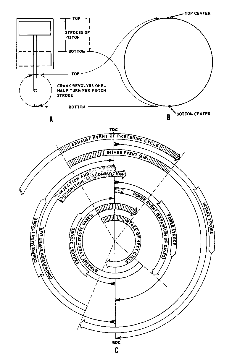
- 4-Stroke Cycle Diesel Engine
- To help you understand the relationship between events and strokes, we will discuss the number of events occurring during a specific stroke. We will also discuss the duration of an event with respect to a piston stroke and the cases where one event overlaps another. We can demonstrate the relationship of events to strokes by showing the changing situation in a cylinder during a cycle of operation. Figure 1 illustrates these changes for a 4-stroke cycle diesel engine.
- The relationship of events to strokes is more readily understood if the movements of a piston and its crankshaft are considered first. In figure l, view A, the reciprocating motion and stroke of a piston are indicated and the rotary motion of the crank during two piston strokes is shown. The positions of the piston and crank at the start and end of a stroke are marked "top" and "bottom" respectively. If these positions and movements are marked on a circle (fig. 1, view B), the piston position, when at the top of a stroke, is located at the top of the circle. When the piston is at the bottom of a stroke, the piston position is located at the bottom center of the circle. Note in views A and B of figure 1 that the top center and bottom center identify points where changes in direction of motion take place. In other words, when the piston is at top center, upward motion has stopped and downward motion is ready to begin. With respect to motion, the piston is "dead." The points which designate changes in direction of motion for a piston and crank are frequently called TOP DEAD CENTER (TDC) and BOTTOM DEAD CENTER (BDC). You should keep TDC and BDC in mind since they identify the start and end of a stroke and since they are the points from which the start and end of events are established.
- By following the strokes and events as illustrated, you can see that the intake event starts before TDC or before the actual downstroke (intake) starts, and it continues on past BDC or beyond the end of the stroke. The compression event starts when the intake event ends, but the upstroke (compression) has been in process since BDC. The injection and ignition events overlap with the latter part of the compression event, which ends at TDC. The burning of the fuel continues a few degrees past TDC. The power event or expansion of gases ends several degrees before the downstroke (power) ends at BDC. The exhaust event starts when the power event ends, and it continues through the complete upstroke (exhaust) and past TDC. Note the overlap of the exhaust event with the intake event of the next cycle. The details on why certain events overlap and why some events are shorter or longer with respect to strokes will be covered later in this lesson.
- From the preceding discussion, you can see that he term stroke is sometimes used to identify an event that occurs in a cycle of operation. However, you should keep in mind that a stroke involves 180°
of crankshaft rotation (or piston movement between dead centers), while the corresponding event may take place during a greater or lesser number of degrees of shaft rotation.
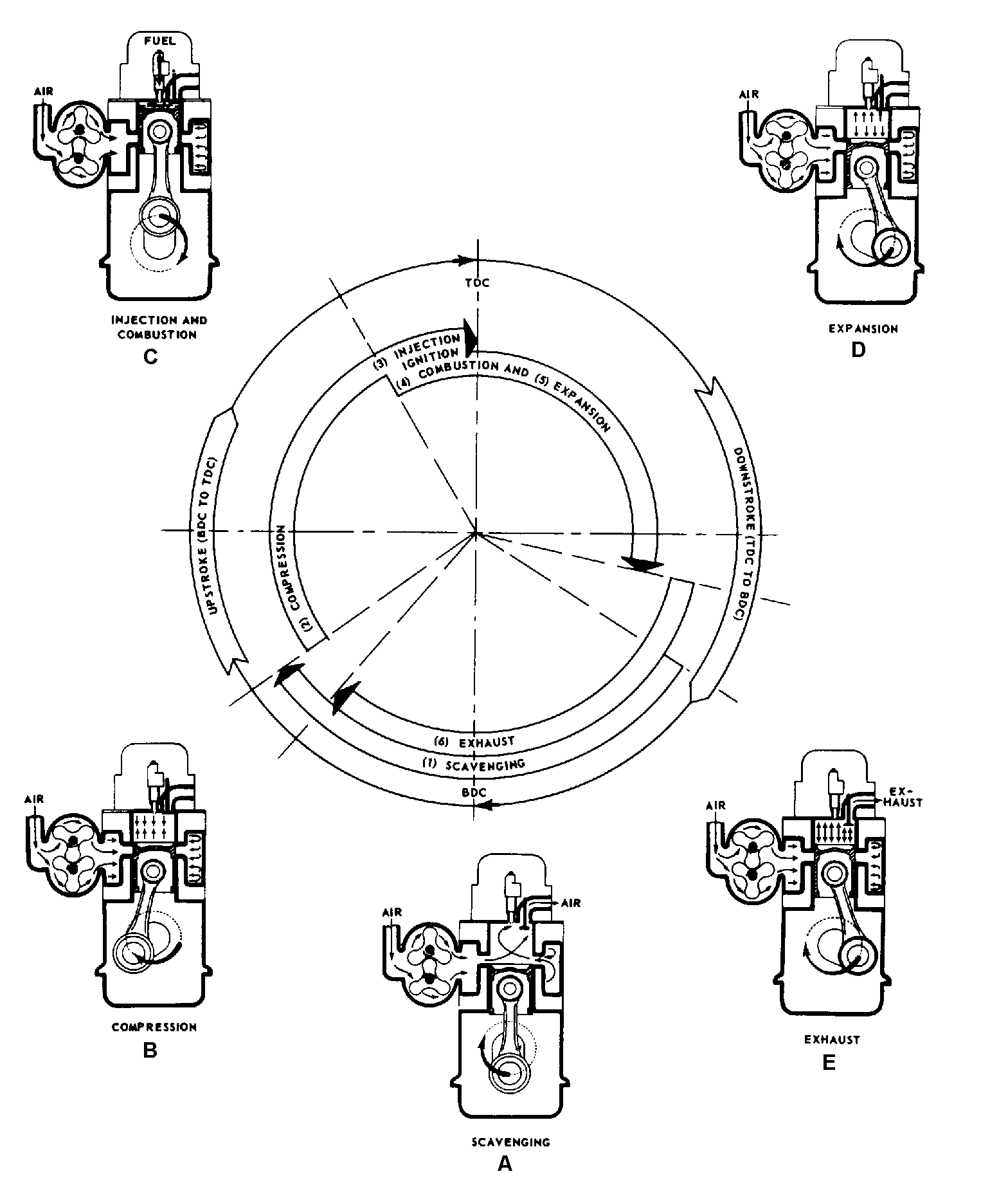
- 2-Stroke Cycle Diesel Engine
- The relationship of events to strokes in a 2-stroke cycle diesel engine is shown in figure 2. Comparison of figures 1 and 2 reveals a number of differences between the two types of mechanical or operating cycles. These differences are not too difficult to understand if one keeps in mind that four piston strokes and 720° of crankshaft rotation are involved in the 4-stroke cycle, while only half as many strokes and degrees are involved in a 2-stroke cycle. Reference to the cross-sectional illustrations (fig. 2) will aid in associating the event with the relative position of the piston. Even though the two piston strokes are frequently referred to as power and compression, they are identified as the downstroke (TDC to BDC) and upstroke (BDC to TDC) in this discussion to avoid confusion when reference is made to an event.
- Starting with the admission of air (figure 2), during the scavenging event (A), we find that the piston is in the lower half of the downstroke and that the exhaust event (E) is in process. The exhaust event started a number of degrees before intake, both starting several degrees before the piston reached BDC. The overlap of these events is necessary so that the incoming air (A) can aid in clearing the cylinder of exhaust gases. Note that the exhaust event stops a few degrees before the intake event stops, but several degrees after the upstroke of the piston has started. (The exhaust event in some 2-stroke cycle diesel engines ends a few degrees after the intake event ends). When the scavenging event ends, the cylinder is charged with the air that is to be compressed. The compression event (B) takes place during the major portion of the upstroke. The injection event and ignition and combustion event (C) occur during the latter part of the upstroke. (The point at which the injection ends varies with engines. In some cases, it ends before TDC; in others, a few degrees after TDC). The intense heat generated during the compression of the air ignites the fuel-air mixture, and the pressure resulting from combustion forces the piston down. The expansion (D) of the gases continues through a major portion of the downstroke. After the force of the gases has been expended, the exhaust valve opens (E) and permits the burned gases to enter the exhaust manifold. As the piston moves downward, the intake ports are uncovered (A) and the incoming air clears the cylinder of the remaining exhaust gases and fills the cylinder with a fresh air charge (A); thus, the cycle of operation has started again.
- Comparison of 2-Stroke and 4-Stroke Cycle Diesel Engines
- During the same amount of time, a 2-stroke engine will have two power events while a 4-stroke engine will have only one. This might lead you to believe that 2-stroke engines are more efficient than 4-stroke engines; however, that is not the case. To work properly, a 2-stroke engine must have some method of forcing air into and through the cylinders. And, since this air pump (blower) is driven by the engine, it robs some of the horsepower that would otherwise be available to drive the load. Also, the combustion process in a 2-stroke engine is not as complete as it is in a 4-stroke engine. Since each type of engine has certain advantages over the other, the Navy uses both 2-stroke and 4-stroke cycle engines for main propulsion and electrical generating service.
- The figures we have used to represent the cycles of operation are for illustrative purposes only. The exact number of degrees before or after TDC or BDC at which an event starts and ends will vary among engines. You can find information on such details in appropriate technical manuals dealing with the specific engine in question.
- Combustion Cycles
- Up to this point, we have given greater consideration to the strokes of a piston and the related events taking place during a cycle of operation than we have to the heat process involved in the cycle. However, we cannot discuss the mechanics of engine operation without dealing with heat. Such terms as ignition, combustion, and expansion of gases indicate that heat is essential to a cycle of engine operation.
- So far, the only difference we have pointed out between diesel and gasoline engines is the number of events that occur during the cycle of operation. We have told you that either the 2-stroke or 4-stroke cycle may apply to both a diesel engine and a gasoline engine. Then, one of the principal differences between these types of engines must involve the heat processes that produce the forces that make the engine operate. The heat processes are sometimes called combustion or heat cycles.
- The two most common combustion cycles associated with reciprocating internal combustion engines are the OTTO cycle (gasoline engines) and the DIESEL cycle (diesel engines). Each of these combustion cycles will be discussed in the following paragraphs.
- In talking about combustion cycles, we must bring up another important difference between gasoline and diesel engines - the difference in compression pressure. Compression pressure is directly related to the combustion process in an engine. Diesel engines have a much higher compression pressure than gasoline engines. The higher compression pressure in diesels explains the difference in the methods of ignition used in gasoline and diesel engines.
- Methods Of Ignition - When the gases within a cylinder are compressed, the temperature of the confined gases rises. As the compression increases, the temperature rises. In a gasoline engine, the compression temperature is always lower than the point at which the fuel will ignite spontaneously. Thus, the heat required to ignite the fuel must come from an external source spark ignition. On the other hand, the compression temperature in a diesel engine is far above the ignition point of the fuel oil; therefore, ignition takes place as a result of the heat generated by the compression of the air within the cylinder compression ignition.
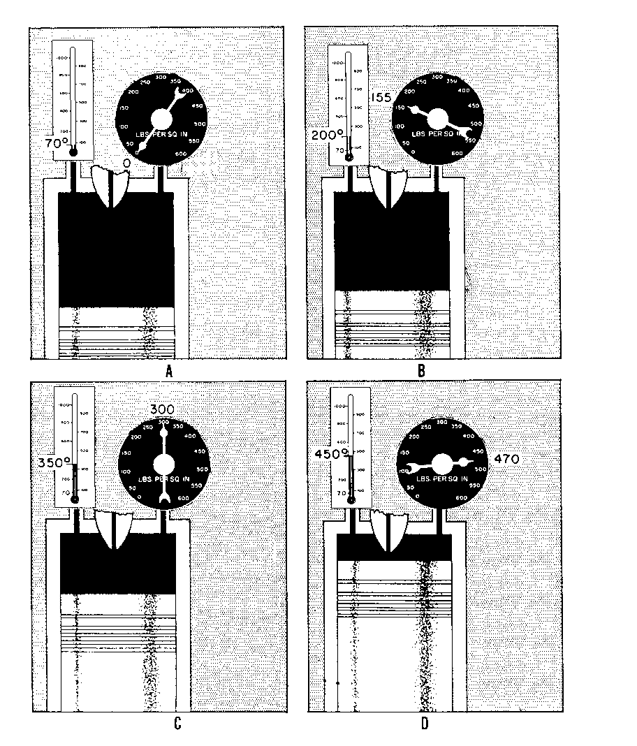
- The difference in the methods of ignition indicates that there is a basic difference in the combustion cycles upon which diesel and gasoline engines operate. This difference involves the behavior of the combustion gases under varying conditions of pressure, temperature, and volume. Since this is so, you should be familiar with factors before considering the combustion cycles individually.
- Relationship of Temperature, Pressure, and Volume - The relationship of temperature, pressure, and volume as found in an engine can be illustrated by a description of what takes place in a cylinder that is fitted with a reciprocating piston. Follow views A through D of figure 3. In view A, note that the instruments that indicate the pressure within the cylinder and the temperature inside the cylinder show the temperature as approximately 70°F. Assume that it is an airtight container, as it is in our example. Now compare views A and B of figure 3. If a force pushes the piston toward the top of the cylinder, the entrapped charge will be compressed. In views B and C, the compression progresses. The volume of the air decreases, the pressure increases, and the temperature rises. These changing conditions continue as the piston moves. When the piston nears TDC in view D, there has been a marked decrease in volume. Also, both pressure and temperature are much greater than at the beginning of compression. Notice that pressure has gone from 0 psi to 470 psi and the temperature has increased from 70°F to approximately 450°F. These changing conditions indicate that mechanical energy, in the form of force applied to the piston, has been transformed into heat energy in the compressed air. The temperature of the air has been raised sufficiently to cause ignition of fuel that is injected into the cylinder.
- Further changes take place after ignition. Since ignition occurs shortly before TDC, there is little change in volume until the piston passes TDC. However, there is a sharp increase in both pressure and temperature shortly after ignition takes place. The increased pressure forces the piston downward. As the piston moves downward, the gases expand (increase in volume), and pressure and temperature decrease rapidly. These changes in volume, pressure, and temperature are representative of the changing conditions in the cylinder of a diesel engine.
- Otto (Constant-Volume) Cycle - In theory, the Otto combustion cycle is one in which combustion, induced by spark ignition, occurs at constant volume. The Otto cycle and its principles serve as the basis for modern gasoline engine designs.
- Diesel (Constant-Pressure) Cycle - In the diesel cycle, the burning of the mixture of fuel and compressed air is a relatively slow process when compared with the quick explosive type of combustion process of the Otto cycle. In the diesel engine, the injected fuel penetrates the compressed air, some of the fuel ignites, then the rest of the charge burns. The expansion of the gases keeps pace with the change in volume caused by piston travel. Thus, combustion is said to occur at constant pressure.
- The preceding paragraphs have pointed out some of the main differences between engines that operate on the Otto cycle and those that operate on the diesel cycle. In brief, these differences involve (1) the mixing of fuel and air, (2) the compression ratio, (3) the method of ignition, and (4) the combustion process.
- Engine Classification
- Diesel engines are also classified on the basis of cylinder block construction and cylinder arrangement (in-line, V or opposed piston) as shown in figure 4.
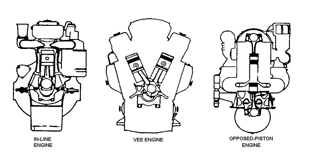
- Single acting engines (in-line and V) have only one piston per cylinder. The combustion gases act on one surface-the crown (top) of the piston. The crown is the closed end of the barrel or wall of the piston, the skirt is the open end. The crown serves as the lower moving wall of the combustion chamber, and the crown is the piston surface acted upon by the combustion gas. The skirt provides directional stability to the piston as it slides up and down in the cylinder, and absorbs piston side thrust which results from the off center loads imposed by the articulated motion of the connecting rod. Since the gas pressure acts only against the top of the crown, the engine is described as single acting.
- Those engines having two pistons in each cylinder are classified as opposed piston. The pistons are arranged crown to crown with the combustion chamber now located in the space between their two crowns (see figure 5). When combustion takes place, the gases act against both piston crowns, driving them in opposite directions. In this type of engine, two crankshafts are required for transmission of power and both shafts contribute to the engine output. In order to maintain the relative position of the two pistons in each cylinder during the cycle events, the two crankshafts are geared to one another by a vertical drive shaft.
- Opposed-piston engines have scavenging (intake) air ports located near the top of the cylinders. These ports are opened and closed by the upper piston. Exhaust ports, located near the bottom of the cylinder, are closed and opened by the lower piston.
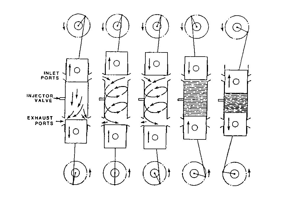
- Because the pistons in these engines are acting as the scavenging and exhaust valves, the valves and valve train found in single acting engines are not required.
- Movement of the opposed pistons is such that the crowns are close together near the center of the cylinder. Figure 5 shows the sequence of two stroke cycle events in the opposed piston engine.
- Opposed-piston engines have a number of advantages over single acting engines of a comparable rating. Some of these advantages are: less weight per horsepower developed; lack of cylinder heads and valve mechanisms (and cooling and lubricating problems associated with them); and fewer moving parts. They are used both in SSDG and EDG applications in the Navy.
- Engine Components
- Stationary Parts
- The stationary diesel engine components maintain the moving engine parts in their proper relative position. These components include the cylinder block and the cylinder assembly. The cylinder assembly is composed of the cylinder head and liner. The cylinder block supports the engine's cylinders and head(s). The sump or oil pan is attached to the block and is the reservoir for collecting the engine's lubricating oil.
- The cylinder assembly confines and releases the combustion gas. It consists of the head, the liner, the studs and gasket. The components provide a gas tight, liquid tight space.
- Diesels with the exception of the opposed-piston type have the combustion end of the cylinder sealed by a cylinder head. A number of engine parts essential to engine operation may be found attached to or around the head. Some of these parts are: intake and exhaust valves, rocker arm assemblies, fuel injector valves, air starting valves, indicator and blow down valves and safety valve. The head is water cooled and so it has water piping connections as well. It is usually bolted to the upper end of the cylinder liner and the complete assembly bolted or clamped into the cylinder block. The head gasket, the seal between the head and cylinder liner, is critical and subject to gas cuts if not correctly made.
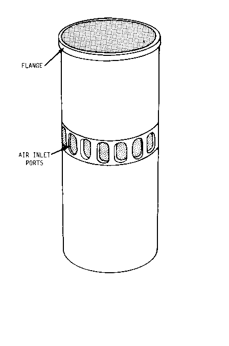
- Cylinder liners fall into three categories: dry, wet or jacket type. This classification describes whether the liner has no contact with jacket water (dry liner), forms one side of the jacket water passage (wet liner), or completely encapsulates the jacket water passage surrounding the liner (jacket liner). Liners are secured at their upper ends to the head and form a sliding joint with the block at their lower ends to allow for thermal expansion. They are typically fabricated from grey iron or other similar material which has some surface porosity to assist in maintaining a constant lube oil surface film during operation. The cylinder liner provides scavenging ports in two stroke engines (figure 6). In opposed piston engines the liner will have scavenging and exhaust ports, injector, air start and indicator ports.
- Principal Moving Parts
- These are divided into three major groups:
- parts which only have reciprocating motion (pistons),
- parts which have reciprocating and rotary motion (connecting rods)
- parts which only have rotating motion (crankshaft and camshaft).
- Pistons (figure 7)
- Pistons must be strong enough to withstand the pressures of combustion and light enough to minimize inertial loads. Pistons are therefore usually fabricated from cast iron or aluminum in one or two pieces. Piston rings snap into position in grooves located in two groups, one near the crown and one at the lower end of the skirt. The upper piston rings (compression rings) seal the cylinder. The compression rings also provide a path to conduct heat from the piston to the cylinder liner so that it may be removed by circulating jacket water. The lower rings (oil rings or oil scraper rings) serve to distribute lube oil and remove excess oil from the cylinder liner walls.
- Almost all diesel pistons use internal oil flow to remove combustion heat from the piston crown. To do this internal passages are provided to bring pressurized oil from the main bearings through the crankshaft, crankpin, connecting rod and piston pin into the piston crown. This oil absorbs heat and then drains to the engine sump by gravity.
- The piston pin connects the piston to the connecting rod.
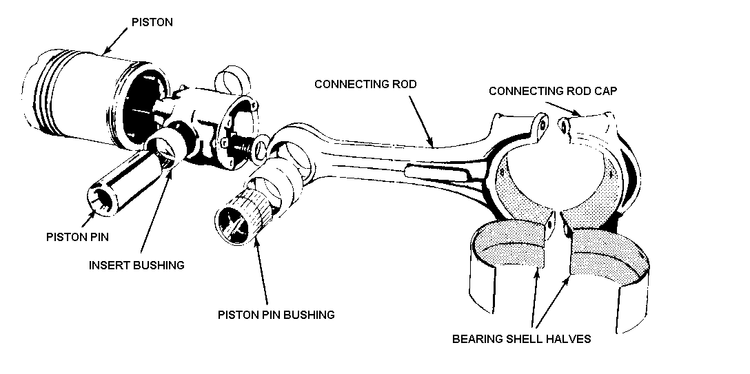
- The connecting rod transmits the reciprocating motion of piston to the crankshaft crank pin, generating the rotary motion of the crankshaft. Connecting rods are subjected to severe cyclical tension and compression loads (4 stroke engines) and to cyclical compression loads only (2 stroke engines). To provide adequate toughness, they are typically formed from steel forgings which are heat treated to improve fatigue resistance. The piston pin bearing is usually a sleeve type bearing.
- Camshafts (figure 8) are component actuating drives which are timed by gear or chain drives to the crankshaft (and therefore piston) position. Camshafts are configured with eccentric projections called cams whose shape controls the operation of valves and injectors by varying the position of the components intermediate linkage (train). The camshaft is usually driven by the crankshaft through a geared or chain drive connection.
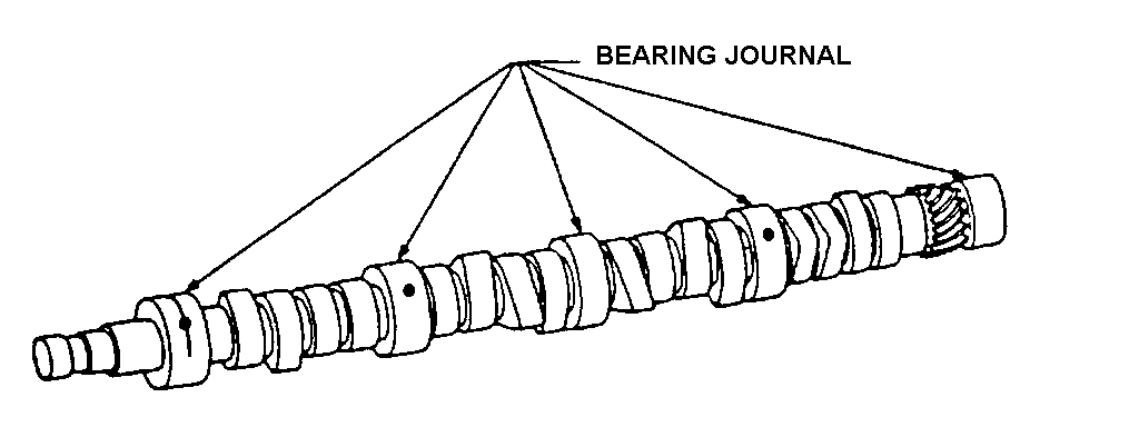
- The crankshaft (figure 9) changes the movement of the pistons and connecting rod into the rotary motion required for the engine output. The crankshaft is subjected to a wide variety of forces in the engine, so it must be ruggedly built to withstand the stress. Crankshafts may be constructed of one or several pieces . The crankshaft will consist of the main bearing journals arranged along the shaft's axis and interspaced between crankthrows for each cylinder or cylinder pair (in V-type engines, connecting rods for cylinder pairs are connected to the same crankpin).
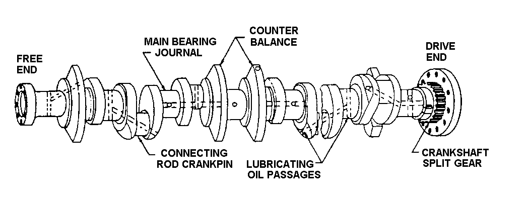
- The crankthrow consists of two webs and a journal (crankpin) to which the connecting rod (or rods in V-type) lower bearing is connected. Because of the pulsed power as each cylinder fires, crankshafts are sometimes equipped with flywheels for smoother power delivery. Flywheels add extra mass which absorbs the pulsed energy and by virtue of inertia gives up that energy in a steady release. In those engines without flywheels, the additional inertial mass is added by distributing it along the entire length of the crankshaft. Other crankshaft attachments include counter or balancing weights, drive gears, flexible couplings, and oil flinger rings.
- The main bearings of the diesel engine support the crankshaft. These bearings are either babbitted or aluminum. The most common location for these bearings is in the bottom of the engine block where the bearing caps bolt the underslung crankshaft up into the block which supports it. The main bearings are lubricated by pressurized engine lube oil supplied by the attached lube oil pump. Once processed by the components of the external lube oil system, lube oil is delivered to the bearings through internal lube oil passages or "galleries" in the engine by a separate line to each bearing cap. Lube oil then flows around and through the bearing and on into the crankshaft.
- Engine Systems
- Engine Combustion Air Intake and Exhaust Systems
- The diesel engine air systems are commonly referred to as the intake and exhaust systems. The air intake system (figure 10 shows a 2-stroke engine) has a turbocharger and/or a blower installed to increase the flow of air to the cylinders. This is accomplished by compressing the air and forcing it into an air box or manifold which surrounds or is attached to the cylinders of the engine. The increased amount of air available is used to fill the cylinder with a fresh charge of air and, in the process, blow through and clear the cylinder of combustion gases. The process of using intake air to flush out exhaust gas is called scavenging.
- An increase in the mass of air flow into the cylinder increases engine power output. This technique is called supercharging. Supercharging, on engines with blowers, turbochargers or both, is accomplished by shutting the exhaust ports (valves) prior to shutting the inlet ports (valves). This places the air in the cylinder at the blower or turbocharger discharge pressure (one to five psig). In some applications, a turbocharger is mounted in series with the blower to increase the air pressure to the cylinder (15 to 25 psig).
- The air intake system also cleans the air and reduces the noise created by the air as it enters the engine. To accomplish this objective the system frequently includes an air silencer and an air cleaner and screen. In small engine systems the air inlet may draw air from the engine space and depend on the installed space ventilation to provide adequate air. In larger engine systems, air is drawn directly from the outside by ducting which serves the diesel alone. In this type system, blow-in doors may be installed to prevent collapsing the system should the air inlet screens become blocked.
- The engine air blower, sometimes referred to as a "roots blower", is a positive displacement lobe type air pump driven off the crankshaft. The turbocharger is a non-positive displacement centrifugal air pump which is driven by exhaust gas.
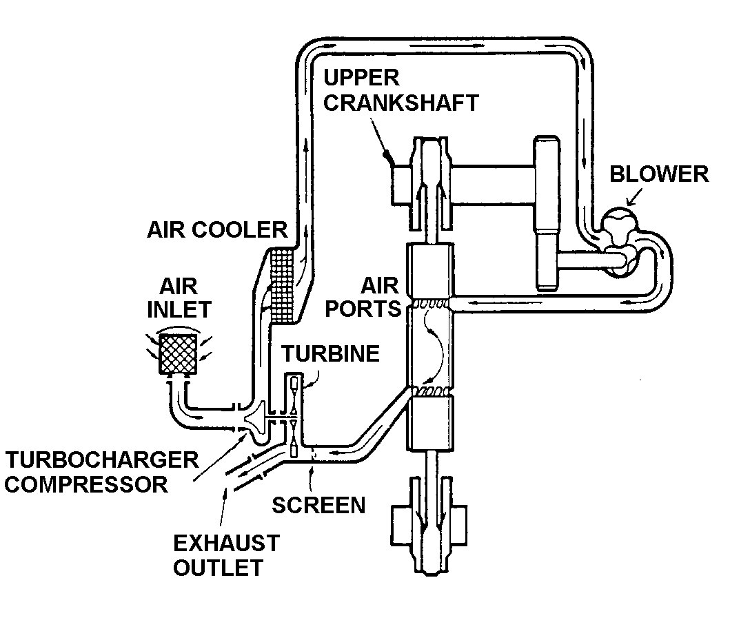
- Many engines with installed turbochargers have coolers installed between the turbocharger and the air manifold. The cooler reduces the temperature of the air which increased as a result of being compressed. Lowering the air temperature increases its density and allows more air to be packed into the combustion chamber, hence more fuel to be burned per cycle. This also increases the power output of the engine. These coolers are termed intercoolers or aftercoolers by engine manufacturers, but all serve the same purpose. Seawater is the usual cooling medium with jacket water used in some instances.
- Engines with a turbocharger and an air blower may have two coolers, one after each stage of air compression.
- The exhaust system conveys the combustion gases away from the cylinders. It also muffles exhaust noise and quenches sparks. In the case where a turbocharger is installed, the exhaust system conveys exhaust gas to the turbocharger turbine inlet where some heat energy is reclaimed by the turbocharger drive turbine prior to exhausting the gas to atmosphere.
- Engine Fuel Systems
- The fuel system delivers fuel to the cylinder under specified conditions. The system controls the quantity of fuel injected, the timing of injection, the rate of injection and distributes the fuel throughout the cylinder for even, thorough mixing and better combustion. A typical arrangement is shown in figure 11. An attached, positive displacement fuel pump takes a suction on the fuel oil service tank through a mechanical strainer. Knife edge strainers are commonly used in this application. The pump discharges through one or more stages of cartridge type fuel filters to the engine fuel oil manifold. The manifold has individual supply lines to each cylinder's injection pump or unit injector.
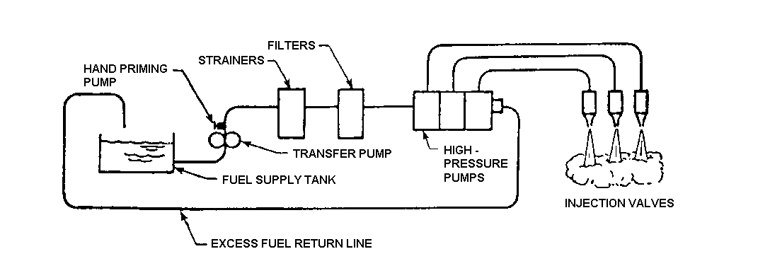
- The diesel injection pump (or unit injector, which combines the functions of pump and nozzle into one unit) is a positive displacement reciprocating pump with a constant stroke that forces fuel at the correct time and in the correct amount into the cylinder for the power level demanded.
- Because of the need for exact timing of fuel injection at the proper moment in the cycle, each cylinder of an engine has at least one (some engines have two) associated injection pump or unit injector.
- The start of injection is initiated by the roll of the injector pump cam on the camshaft. The camshaft position is timed to the position of the piston in the cylinder. The lobe of the cam rolls past the injection pump lifter, moving it up. This action strokes the plunger in the injector pump, moving it up across the barrel inlet port to capture a volume of fuel in the upper barrel chamber.
- The plunger continues to move upward until it pressurizes the fuel to the point that the nozzle poppit valve opens and admits atomized fuel to the cylinder. This valve functions like a relief valve - it will not open until the pressure has built up to the valve's setpoint, usually about 2000 psig. Thus the start of the injection is mechanically fixed (timed) to the piston position. Injection too early causes engine knocking. Late injection results in unburned fuel in the exhaust. So it is important that the start of the injection be precisely initiated by the camshaft action. Fuel continues to be injected into the combustion chamber until the plunger rises to the position where its helical cutout passes the spill port. Fuel in the injector chamber now has an alternate path to follow, down through the slot and helical cutouts in the plunger and out through the spill port to the return fuel line.
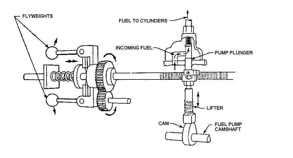
- Power output is controlled by varying the duration of fuel injection. This is accomplished by moving the injection pump rack with the governor control linkage (figure 12). The rack engages the pinion gear teeth on the outside of the control sleeve surrounding the injector pump barrel.
- The control sleeve engages the plunger flange, so it rotates the plunger inside the barrel. This movement reorients the helical cutout in the injection pump plunger with respect to the spill or outlet port in the barrel. By extending or shortening the effective length of the plunger stroke (the actual length of the plunger stroke is constant), the duration of the fuel injection event is changed to suit the power demand.
- The unit injector also functions to provide proper atomization of the fuel and the requisite penetration of the fuel into the cylinder. It does this by expelling fuel to the cylinder through very fine openings and developing a pressure sufficiently above the cylinder pressure to break the fuel into fine particles and impart to it a high kinetic energy in the process of injecting it into the cylinder.
- Where injection pumps with separate nozzles are installed, the pump generates the high fuel pressure for injection, and the fuel flows through a high pressure line to an injection nozzle. It is the nozzle which mechanically atomizes the fuel and injects it into the combustion chamber.
- General Heat Flow
- A means of removing heat from an engine must be provided or the engine would only run for a short time. The temperature of combustion is greater than that at which iron melts. Without proper temperature control, the lubricating oil film between moving parts would be destroyed, proper clearances between parts could not be maintained and metals would tend to fail. 35 to 40% of the potential energy in the fuel is lost up the stack, about 33% accomplishes useful work, and the remainder is removed by jacket water, lube oil and intercooler water as heat.
- Lube Oil Cooling
- The role of lube oil in removing heat and the features in engine construction that support that function have already been discussed. Engine lubrication systems will be further discussed shortly.
- Fresh (Jacket) Water
- The cooling system in direct contact with the engine is the fresh water system, also called the jacket water system. This is a closed system which uses fresh water as the cooling medium. The water is usually treated with some type of corrosion inhibitor. Installations on small boats which are subject to freezing temperatures use antifreeze instead of corrosion inhibitor. Water flow is established by an attached centrifugal pump and flows through a jacket water cooler where it gives up heat to seawater, then to the lube oil cooler where it gains heat from lube oil.
- Waste Heat
- In ships which use jacket water as a source for waste heat, a waste heat exchanger may be placed in parallel with the jacket water cooler to provide a path through which the heat given up by jacket water may be reclaimed for ship service use, such as heating potable water or distilling fresh water. If such a parallel installation is provided, a proportioning valve will be installed to manage the flow through both heat exchangers to insure that jacket water temperature does not exceed its maximum limit while maintaining the minimum waste heat temperature. Jacket water will then flow into the engine and through the cooling passages around the cylinders, in the heads and around exhaust manifolds, injector nozzles, turbochargers, etc., before returning to the pump suction. An expansion tank connected to the system is vented to the atmosphere and allows system fluid thermal expansion as well as providing a point at which water or chemical treatment may be added.
- Keep warm System
- Some engines have a keep warm system which uses an electrical heater to warm jacket water to allow easy engine starts and rapid loading after starting because the engine is quickly at normal operating temperature.
- Seawater
- The seawater or raw water cooling system is an open system which removes heat from the jacketwater cooler, generator air cooler (on an SSDG or EDG) and any intercooler/aftercooler installed, and carries it overboard. Flow in the raw water system is also established by an attached centrifugal pump taking suction on a seawater service line, firemain or its own dedicated sea chest suction. The sea water flows out of the pump through the jacketwater cooler and after/intercooler absorbing heat. It then is piped directly overboard.
- Engine Lubrication Systems
- The engine lubrication system consists of two main divisions, one external to the engine and the second internal.
- The internal division consists principally of passages and piping (called galleries) to distribute oil to bearings and surfaces where it is required throughout the engine, and to passages and drain lines which return oil to the oil pan.
- The external portion includes components which aid in supplying oil in the proper quality, at the proper temperature, and free of impurities. To accomplish the latter, the external system consists of sumps or tanks, pumps, coolers, strainers and filters, and purifiers.
- Diesel engine lubricating oil systems are the pressurized type, and are usually described by the path of oil flow with respect to the system filter. Full flow systems force all the pump output through the filter on every pass.
- Diesels are configured with either wet or dry sumps. Wet sump diesels use the engine oil pan to store the working reservoir of lube oil. Dry sump diesels employ an unattached tank to store the lube oil reserve, and must have a scavenging pump to remove oil as it collects in the oil pan and pump it to the remote sump tank.
- A prelube pump may be installed in any diesel engine to lubricate the engine prior to starting.
- Navy ships use 9250 for diesel engine lube oil. This oil is designed for use in internal combustion engines and has different properties from the lubricating oils used in steam and gas turbine applications. As in any lube oil system, cleanliness is critical to continued engine operation. Engine bearings in particular are subject to damage if particulate contamination enters the system, since it blocks lube oil flow through passages and scores bearing surfaces, thus disrupting the lubricating oil film separating bearing and journal surfaces. The result is increased friction and wear, or in the worst case, catastrophic failure of the engine component.
- Engine Start Systems
- The diesel engine start system may be pneumatic or electric. Start systems may employ an air or electric motor driven starter which engages the flywheel to initiate crankshaft rotation. The motor then disengages when the engine achieves a minimum speed at which rotation is self sustaining.
- An alternative scheme (commonly used in larger engines) is the use of medium pressure (about 500 psig) start air, stored in flasks, which is ported in a timed sequence directly into selected diesel cylinders (figure 13). Here, instead of physically turning the crankshaft, the compressed air forces the pistons to move (in the same order as piston firing during engine operation). The movement of the pistons rotates the crankshaft.
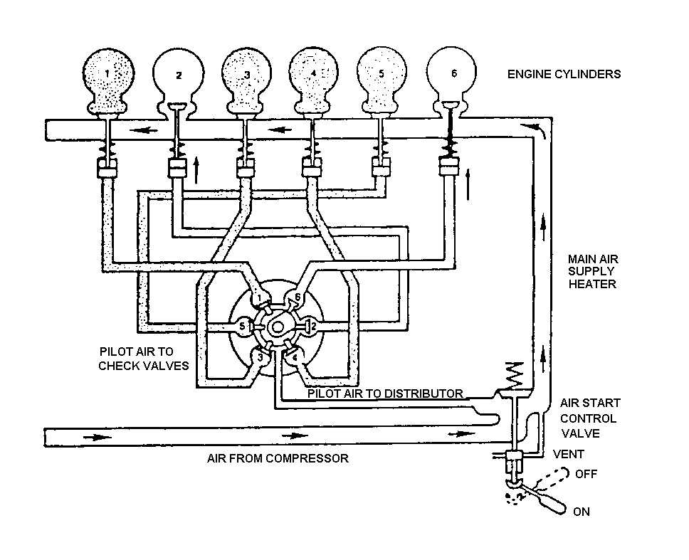
- Virtually all start systems have one or more interlocks to prohibit inadvertent starting in an unsafe condition, such as without initial lube oil pressure or with the barring device engaged.
- Engine Barring Devices
- The barring device is a mechanical component which is used to turn the crankshaft without starting the engine or employing the engine starting system. This is required for maintenance purposes (to place the engine components in a desired position) or to ensure the engine is free to rotate prior to starting. The barring device may be hand, air motor or electric motor driven. Since it must overcome the initial frictional resistance to movement present in the stationary engine, the device must generate a large torque with a relatively small power source. It does this through the mechanical advantage developed by a gearbox, with a consequent substantial difference in input speed versus output speed. To prevent damage to the barring device or its mechanical or human power input when the engine is running, the barring device has both an engaged and a disengaged or safe position.
- Engine Crankcase Evacuation System
- The crankcase evacuation system removes excess air and oil vapor from the engine crankcase; therefore, the engine operates with a slight crankcase vacuum.
- The purpose of crankcase evacuation is to reduce the possibility of a crankcase explosion. With a certain concentration of oil vapor and air in the crankcase, exposure to a significant heat source such as an overheated bearing will ignite the vapor explosively. The crankcase evacuation system provides a method for drawing off the vapor and air in the crankcase to maintain the concentration of volatile fumes in the crankcase below explosive limits. Most systems consist of an eductor or fan arrangement which draws the vapor from the crankcase and exhausts into the engine uptakes, to exhaust ventilation or back into the engine inlet.
- Diesel Engine Operations
- The diesel engine is limited to operating at certain combinations of speed and load by virtue of the strength of its materials under thermal and dynamic stress and capacity to provide adequate air and cooling. Beyond the physical limitations imposed by engine components, the operator also wants to extend the interval between engine overhauls to the maximum possible extent. That end can be achieved by restricting the operating envelope to reduce excessive stress and wear on the engine.
- The power produced by a diesel engine is proportional to the product of the following factors:
- displacement (piston volume times number of pistons)
- speed (number of power strokes per minute)
- cylinder pressure
- Engine displacement is fixed at time of construction, and engine speed for a loaded generator is constant for 60 Hz power. Therefore, the only factor that varies is the cylinder firing pressure (pressure reached inside cylinders during combustion). Cylinder firing pressures (and temperatures) rise as the engine load increases because more fuel is being burned in each power stroke.
- When the engine is light-loaded (below 60 percent load), cylinder firing temperatures are insufficient to completely burn lube oil, leading to carryover of lube oil and formation of hardened carbon deposits in the exhaust system, with resultant restrictions in exhaust system flow and fire hazards. As the engine load drops even further, cylinder temperatures are low enough that not all fuel is burned.
- Unburned fuel mixes with unburned lube oil in the cylinder and can get into the engine sump. (There are other paths for fuel to get into the lube oil sump, including leaks from fuel injection pump discharge lines. This leakage may drain to the lube oil sump. Whatever path taken, this condition is known as fuel dilution of lube oil. This condition is undesirable because fuel lacks the lubricating and cooling properties of lube oil and can result in bearing damage in the engine. Moreover, fuel vapor in the crankcase can lead to a crankcase explosion.
- The following thumb rules apply to diesel engine operation:
- Do not idle diesel engines for extended periods of time. Extended operation at less than 60% load at any speed will result in problems (as discussed above) with carbon formation, fuel dilution of lube oil and oil carryover to the exhaust system due to incomplete combustion. Operation at higher speeds with little or no load will develop these problems more rapidly. If operation requirements necessitate engine operation for periods in excess of thirty minutes at 60 percent load or less, the load should be increased to above 80 percent at the first opportunity.
- An engine should not be operated with an overload. When conditions indicate that the engine is overloaded, the load should be reduced immediately. Overload may be indicated by excessive temperatures, smoky exhaust or excessive firing pressure. Here too, operation is exceeding the material strength or heat resistant properties of components and may lead to shortened engine life or failure.
- Exhaust Smoke Analysis
- Increasing concern and attention is being given to the emissions created during engine operation. The emissions from a diesel engine are both visible and invisible. The invisible emissions include various products of combustion, such as carbon dioxide, carbon monoxide (only a small amount is present because of a large amount of excess air), sulfur dioxides, water and gaseous unburned hydrocarbons.
- The visible emissions from diesel engine exhaust are solid or semisolid particles suspended in the exhaust gases that block, reflect or refract light. These particles comprise uncombusted carbonaceous matter whose source can be either fuel or lube oil.
- Observing the smoke from a stack can tell the operator how the engine is functioning. If the engine is producing abnormal amounts of smoke, engine performance is poor. The color of the smoke indicates the probable cause of the smokiness.
- Black or gray smoke can be caused by incomplete burning of fuel due to high exhaust backpressure or an inlet air restriction, bad fuel or fuel injection problems.
- Blue smoke can be caused by excessive lube oil consumption. The source can be worn or broken rings, high crankcase pressure, leaking oil seals in a turbo or blower, plugged drain holes in pistons, glazed liners or worn valve guides or seals.
- White smoke can be caused by low compression, insufficient fuel (bad injectors), water leakage in cylinder, misfiring cylinders or improper fuel. White smoke can also appear during startup because the temperature is too low in the combustion chamber, causing poor combustion. This is a transient condition-as the engine warms up, the white smoke should disappear. Engine startups where the ambient temperature is low are especially prone to white smoke.
 Engineering Training
 Engineering Training


