ASSIGNMENT SHEET
AVIATION SUPPORT
Assignment Sheet Number 62B-409
INTRODUCTION
Aircraft play an ever-increasing and important role in naval operations at sea. The interface between the aircraft and the ship is complex and extensive. Therefore, the ship's role is just as important as that of the aircraft.
LESSON TOPIC LEARNING OBJECTIVES
Terminal Objectives:
11.0 DESCRIBE and EXPLAIN the function, theory of operation, location, operating parameters, design characteristics and maintenance requirements of shipboard auxiliary systems and support equipment. (JTI:A)
Enabling objectives:
11.64 DESCRIBE the installed aviation and support facilities and the Engineering Department's responsibility for operation and maintenance.
11.65 DESCRIBE the requirements for fueling and defueling aircraft using the shipboard JP-5 system.
11.66 DISCUSS management policies and concerns associated with the aviation support facilities.
11.67 UNASSIGNED; reserved for future use.
11.68 UNASSIGNED; reserved for future use.
11.69 UNASSIGNED; reserved for future use.
STUDY ASSIGNMENT
- Read Information Sheet 62B-409
- Outline information sheet 62B-409 using the enabling objectives for lesson 62B-409 as a guide.
- Answer study scenarios.
STUDY SCENARIOS
You are the Auxiliary Officer aboard an amphibious ship and you head to the flight deck to observe refueling operations in conjunction with upcoming amphibious ops. A CH-46 is inbound for fuel and a fuel oil sample is being taken.
- You notice a small amount of water in the sample. After testing, it is found to contain 10mg/liter of water. Are you concerned? Why or why not?
After taking care of the fuel, you proceed to the control tower to observe the landing of the helo. After entering visual range of the ship, the helo initiates communications with the tower and requests permission to land.
- After checking for satisfactory wind direction and speed, and checking with the pilot house, CIC and the helo deck, the HCO grants permission for the helo to land. In addition to radio communications, what visual indications can the ship provide to help guide the pilot to the deck?
- As the helo makes its approach, several bags blow out on deck. How can the tower visually alert the helo pilot that it is no longer safe to land?
INFORMATION SHEET
AVIATION SUPPORT
Information Sheet Number 62B-409
INTRODUCTION
Aircraft play an ever-increasing and important role in naval operations at sea. The interface between the aircraft and the ship is complex and extensive. Therefore, the ship's role is just as important as that of the aircraft.
REFERENCES
a. Helicopter Operations NWP 42
b. NAVAIRINST 10340.3A
c. Gasoline and JP-5 Fuel Systems NSTM Chapter 542
d. Petroleum Fuel Stowage, Use and Testing NSTM Chapter 541
e NAVOSH Program Manual For Forces Afloat OPNAVINST 5100.19B
INFORMATION
- Aviation Support Systems.
- The extent of a ship's aviation facilities varies with certain factors such as ship mission, types of aircraft operating with the ship, and conditions under which operations are to be conducted. Ships with permanently assigned aircraft must provide extensive operating and support facilities, everything from a landing area with day and night visual landing aids and navigation aids, to fully maintained servicing and maintenance areas with hangar(s) and adequate spare parts storage.
- All classes of ships can support aircraft operations to some degree including Coast Guard and Military Sealift Command ships. Aircraft missions aboard ships will vary with ship class and mission. Some shipboard aircraft missions are:
- Anti-Submarine Warfare (ASW)
- Communications relay
- Anti-Ship Surveillance and Targeting (ASST)
- Rappelling/Vertical employment
- Search and Rescue (SAR)
- Mine Counter-Measures
- Vertical Replenishment (VERTREP)
- Medical Evacuation (MEDEVAC)
- Personnel transfer
- Naval Gun Fire Support (NGFS)
- Aviation support systems uses many different types of lighting equipment to assist in the safe operation of aircraft.
- The stabilized glide slope indicator (SGSI) is an electro-hydraulic-optical landing aid mounted on a stabilized platform, designed for use with aviation facilities on ships. The SGSI allows a helo pilot to visually establish and maintain proper glide slope. The SGSI provides a single bar of either green, amber, or red light. The single bar of light indicates to the approaching pilot if above (green), below (red), or on (amber) the correct glide slope. This equipment uses a internal gyro for reference and develops electronic error signals to control hydraulic cylinders that move the platform in an opposite direction to the ship's pitch and roll axis.
- The horizon reference system (HRS) is a stabilized light bar allowing the pilot to maintain a stable horizon during approach. The system uses an input from the ship's master gyro to compensate for the pitch and roll of the ship and automatically corrects the light bar to maintain a stable horizon.
- Deck edge lights define the periphery of the obstruction free area and are located where required on the peripheral marking.
- Landing lineup lights are installed on the approach to indicate the line of approach which leads to the touchdown circle. The pattern of these lights and the markings are specified for each ship class.
- The deck status light system provides visual indications to the pilot as to the condition of the deck. It consists of a set of three lights.
- Green light - A clear deck situation exists; landing and take-off are allowed.
- Amber light - A precautionary deck situation exists; can engage/disengage rotors only.
- Red light - A fouled deck exists; landing and take-off are prohibited.
- Waveoff lights are located on either side of the SGSI and provide a visual cue signifying an unacceptable landing condition.
- Hangar or structure floodlights are mounted on the bulkhead to illuminate the aft face of a hangar or other structure. They are targeted to properly illuminate specific areas and then bolted into place so they cannot move. They are red in color to maintain night vision.
- Homing beacon (white) is located high on the superstructure (usually on the mast) and acts as a reference for locating the ship.
- Control Console (CC)
- The CC is the primary controlling station for all aviation functions and evolutions. The Landing Signals Officer (LSO) can monitor and control the aviation system operation as well as controlling the deck status lights, ready deck signals, flight deck communications, and the installed AFFF sprinkler system.
- The LSO booth is also equipped with a communications set that allows the LSO to utilize ship sound-powered phone systems, interphones and radiotelephone net.
- Flight deck facilities
- The following facilities are provided in the helo control station and in the pilot house:
- Visual landing lighting controls
- Helo crash alarm circuits
- CO's ready deck signal circuit
- Radio set control
- UHF radio channel selector switch
- Radio amplifier
- Radio loudspeaker
- Sound-powered phones (circuit 1JG)
- 5MC announcing system
- Visual Landing Aid (VLA) lights controlled are:
- Hangar (or other structural) illumination floodlights (red)
- Deck surface floodlights (red)
- Extended line-up lights
- Vertical drop-line lights
- Flash sequencer (wired into line-up light circuit)
- Maintenance floodlights (red)
- Helo in flight refueling (HIFR) lights (red)
- Homing lights
- Deck edge lights (red)
- Stabilized glide slope indicator
- Wave-off lights
- Unidirectional line-up lights
- Duplex directional line-up lights (forward VERTREP station only)
- Touch-down lights (green)
- Horizon reference system
- Facilities are provided for helo landing and take-off at the flight deck area aft, and for cargo drop-off at the forward VERTREP area. Each ship has a hangar with the door facing toward the flight deck aft. Fueling and defueling gear is stowed in the helo fueling room or the hangar. Hinged type safety nets are installed along port and starboard deck edges from the hangar area aft.
- Handling and servicing
- Handling gear consists of deck fittings installed in the landing, and parking and hangar areas which serve as flush deck and high-point tie-down fittings. No provision is made for moving the aircraft other than the traversing system. Aircraft cannot be moved by hand. A 3,000-lb air-operated chain hoist, portable davit and padeyes with block and tackle are used in handling and interchanging helo components.
- Helo servicing cables are used to supply 400 Hz AC electrical power for servicing the aircraft. This power supply is delivered through permanently installed cables to terminal boxes which are in turn connected to portable cables and connectors to service aircraft in their normal landing position in the hangar. Mobile electric power units are also used.
- The hangar also contains 60 Hz AC (rectified to DC) cables for starting aircraft.
- An HP air charging station is also provided to charge the sonobuoy launcher on the ASW aircraft.
- Fire protection
- Forward VERTREP, aft landing area and the hangar are protected by permanently installed AFFF systems. AFFF hose-reels are in the hangar areas and used independently or in conjunction with the installed sprinkler system.
- Each hose-reel has 125 ft of hose and a 2Ĺ-inch vari-nozzle.
- Portable 15-lb CO2 fire extinguishers are stowed at VERTREP areas and in the hangar.
- Dry chemical (PKP) fire extinguishers are provided in the following areas:
- 2 in each helo crash-rescue locker
- 2 at the forward VERTREP area
- 2 at each side of the aft VERTREP area
- Crash and rescue/flight quarters manning
- 2 hot-suit men
- 3 hose teams (5 people each including plugman)
- 2 on-scene leaders
- 1 AFFF station operator
- 1 LSE (Landing Signals Enlisted)
- 1 Helo Control Officer
- 1 landing signalman enlisted
- 2 fueling systems operators
- 4 chock and chain personnel
- 1 flight deck phone talker
- Aviation Fueling System
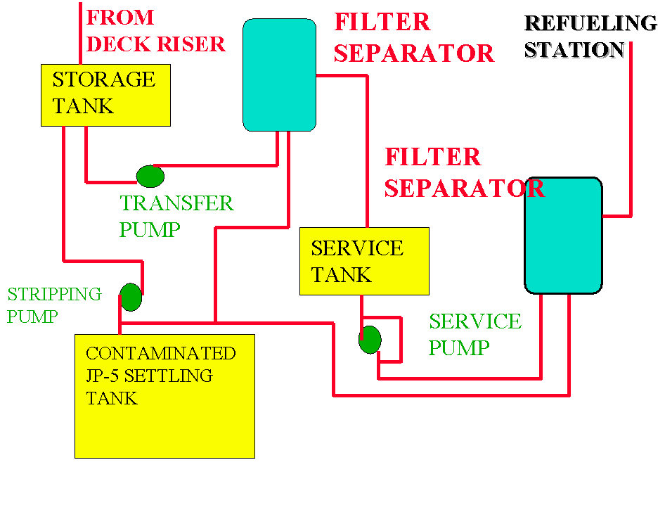
- The aviation fueling system ( see Figure 1) provides JP-5 for fueling of aircraft, and provides for the storage, and transfer of fuel throughout the system. It can also provide fuel for the fueling of small boats, and for the Auxiliary fueling system.
Aviation Fueling System
Figure 1
- Transfer components include a transfer pump and a filter/separator assembly. The filter/separator removes entrained water and dirt from the JP-5.
- The service system is used to deliver fuel to the helo station hose-reel. The filter/separator and pump can be used to recirculate the on-line service tank. A hose flushing connection is located in the hose reel room. The hose shall be flushed for a minimum of two minutes and a sample taken prior to delivery to the aircraft. Flushed fuel is returned to storage tanks.
- The JP-5 stripping system has an electric pump for stripping storage and service tanks . A hand pump is provided for stripping the service tanks. Prior to placing any service tank on suction, the tank shall be hand stripped. The stripping system can also take a suction on the filter/separator assemblies.
- On-deck helicopter fueling, on-deck refueling with engines operating (hot refueling), and Helo In-flight Refueling (HIFR) shall be conducted in accordance with NAVSEA S9542-AA-MMO-010, and NSTM Chapter 542.
- The four types of nozzles used in fueling operations are the Gravity Flow Nozzle, D-1 and D-1R Pressure Fueling Nozzle, and the Closed Circuit Refueling Nozzle (CCR).
- The D-1 (see Figure 2) is a 2 1/2 inch nozzle which has no means of controlling the discharge pressure leaving the nozzle. This nozzle has the ability to both refuel and defuel the helicopter. It is the most common nozzle used for on deck refueling.
- The D-1R nozzle (see Figure 3) is the D-1 fitted with a hose end pressure control valve (HEPCV) to maintain a 55 psi delivery rate to the aircraft.
D-1 Nozzle D-1R Nozzle
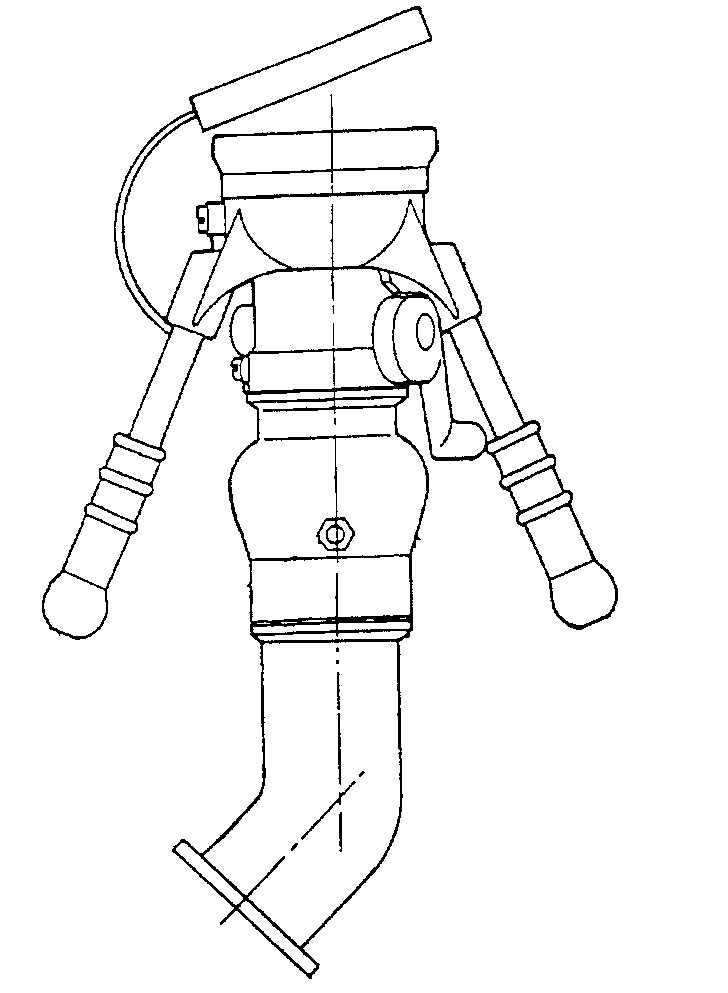
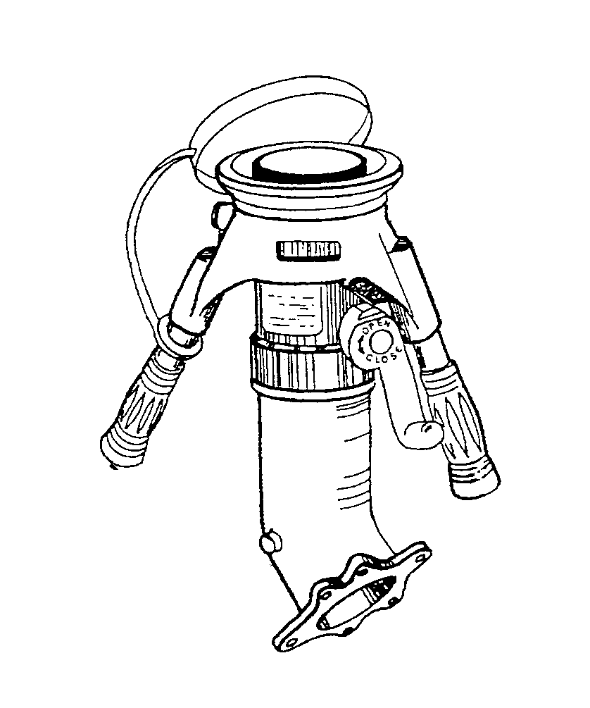
Figure 2 Figure 3
- The closed-circuit refueling (CCR) nozzle (see Figure 4) is equipped with a 45 psig pressure regulator as well as connections for closed-circuit communication used for normal HIFR operations.
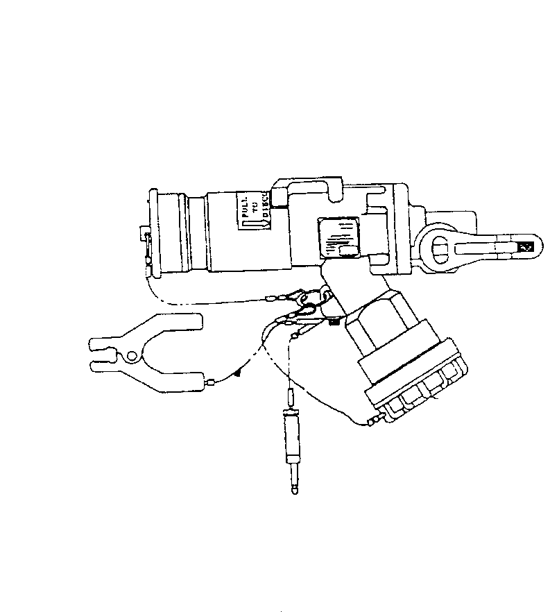
CCR Nozzle
Figure 4
- The 1 1/2 inch gravity flow nozzle (see Figure 5) is used when use of another nozzle is not appropriate. It is also used for refueling small boats and flight deck equipment.
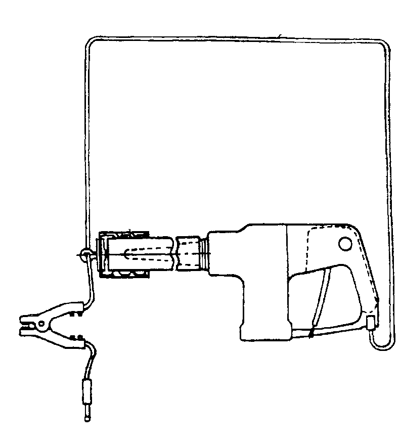
1 1/2 inch Gravity Flow Nozzle
Figure 5
- Before fueling hoses are connected to the helo, the grounding strap or cable must be attached securely to the ship. As the helicopterís rotors rotate, friction is created causing a static charge to be created on the skin of the helo. If this static charge is not correctly grounded to the hull of the ship the resulting discharge could result in both a fire and a shock hazard to the personnel handling the hose.
- Helo defueling is accomplished using an air-operated pump. Clean fuel is directed to a JP-5 storage system and dirty fuel is directed to the stripping system.
- JP-5 fuel is stringently controlled. Any fuel for refueling an aircraft must meet clear and bright criteria.
- Maximum free water contamination - 5 mg/liter
- Fuel special icing inhibitor (FSII) is added to prevent fuel icing at higher helo altitudes.
- Certification of aviation facilities
- Certification requirements:
- Whether it's an air-capable ship with only ship's company, or an amphibious assault ship handling 30 helicopters and V/STOL aircraft, the CNO requires and fleet operations demand that aviation facilities be maintained in a safe and ready condition.
- The CNO, in response to fleet needs, promulgated the requirement for the certification of aviation facilities in naval ships operating with aircraft.
- To accomplish this, the Chief of Naval Material was tasked to establish responsibilities, procedures, and technical guidelines for mandatory certification of all ships with afloat aviation facilities.
- NAVMAT assigned the responsibility to the NAVAIRSYSCOM and NAVSEASYSCOM to achieve and support the objectives of the certification program; NAVMAT maintains direct liaison with fleet commanders on certification matters.
- NAVAIR, in cooperation with NAVSEA and various fleet and shore commands, developed the Bulletin Nr. 1 series for both air-capable and amphibious assault aviation ships. The bulletin defines the facilities required on each type and class of ship necessary to support aircraft operations as specified by the CNO.
- The Ship and Shore Installations Division of NAVAIR administers the certification program, while Naval Air Warfare Center (NAWC), Lakehurst, N.J., is the field activity responsible for the design, inspection and certification of the ship's aviation facilities.
- The basic requirements of the certification program are contained in the following documents:
- OPNAVINST 3120.38 - Certification of Aviation Facilities in Naval Ships Operating Aircraft. This instruction establishes the requirement that all aviation facilities shall be formally inspected and certified as providing proper, adequate and safe facilities in naval ships which operate aircraft.
- OPNAVINST 3120.35 - Helicopter Certification Requirements for Air Capable Ships. This instruction promulgates the level, class, and helicopter type requirements for air capable ships.
- NAVMATINST 3120.1 - Procedures and Responsibilities for the Certification of Aviation Facilities in Naval Ships Operating Aircraft. This instruction establishes the procedures for determining when certification is required, and delineates the responsibilities for accomplishing the certification program to the Naval Air Systems Command and the Naval Sea Systems Command.
- BULLETIN NO. 1 Series - Air Capable Ship Aviation Facilities & Amphibious Assault Ship Aviation Facilities. This bulletin establishes the detailed technical requirements for certification of operating facilities on air capable ships.
 Engineering Training
 Engineering Training


