Publication Date: 16 February 1996
System Version: GCCS 2.1/Update 4
Web Page Created: 15 March 1996
Setup. To accomplish this lesson, you need GCCS connectivity and access to the JOPES database and applications (Session Manager, System Services, IMS, RFM, and FTPtool). USERIDs should have Plan Creator (CRT), Update (UPD), Site Functional Manager (SFM), and Network Functional Manager (NFM) permissions. USERID (user account) must be a member of the UNIX groups (site specific - it's GCCS and JADMIN for the JTO server) to execute the Journalling subsystem, the TP/TDS Management subsystems and the Local OPLAN Database Cleanup (DBA function). You will also need access to an XTerm and run remote window. For the audit section of this lesson, the instructor must add ULN 9BLCK (Service = F) to OPLAN 9096M and ensure auditing is active. The instructor can use RDA or the Merge a TPFDD of SS to accomplish the action. It must be done early enough (prior to the audit portion of this lesson) so that the Journalling subsystem performs at least an Auto Journal operation prior to teaching audit. The user's account must also have Telnet system permissions. One blank 8mm cassette for the class and a formatted DOS 3.5" floppy disk for each student must be available to archive plans/TPFDDs. A GCCS IBM compatible PC with PC-NFS will be used to transfer files to a floppy. Master training OPLANs must be available in the site's JOPES database.
Now that you have an idea of what the subject under discussion will be, the lesson continues by laying some basic groundwork for understanding how transactions are processed.
OBJECTIVE. From a list of possible definitions, select the one that best describes the way that updates to the JOPES database are processed.
The more complicated the command, the greater the number of transactions. For example, setting C-Day or modifying the LAD of a requirement will generate a small number of transactions (maybe only one). If you were to use the merge capability and the TPFDD being merged contained 600 to 700 requirement records, then the merge command would generate a large number of transactions (maybe thousands) requiring processing.
For now, you need to get the "big picture" for database transaction processing. As the lesson continues you will receive additional detail.
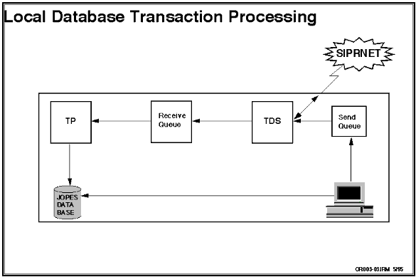
TDS. TDS reads the send queue transactions and forwards those that require distribution and stores those that do not. The TDS also receives transactions from other sites for disposition.
Incoming TDS Transactions. The local TDS will handle transactions sent from a remote site to your site. This is how a remote site updates a network OPLAN resident at your site.
Receive Queue. Like the send queue, the receive queue is a holding area.
Transaction Processor. The receive queue stores transactions until the Transaction Processor (TP) is ready to process the transactions. The TP then sends the transactions to the local JOPES database.
Now that you have the big picture of transaction processing, you should be ready to review the types of transactions processed by JOPES.
| TYPES OF TRANSACTIONS | |
|---|---|
| Type | Definition |
| DESCDT | Adds/Deletes description records to FMID field. |
| INDXDT | Adds/Deletes ULNs, PINs, CINs, and index pointers for FMID for specified plan. |
| TITLDT | Adds title line narrative for FMID and deletes index pointers for ULNs, PINs, and CINs for specified FMID. |
| DLFMDT | Deletes FM from specified plan without deleting requirements. |
| JJDSDT | Accepts data from TPFDD sources that add FM title, description, ULN, PIN, and CIN for specified plan. |
| STRYDT | Deletes FM from specified plan. Includes associated unit and nonunit requirements, and cargo and carrier manifest records. |
| CNTRDT | Puts record counts (number of ULNs, PINs, and CINs in FMID) in the FM table(s). |
| DATEBT | Modifies all dates in entire OPLAN. |
| ULNUBT | Creates, modifies, and deletes force requirement records for a given plan. |
| NRNUBT | Updates nonunit related cargo and personnel records in requirements table(s). |
| NSCGBT | Updates nonstandard cargo information for a given requirement. |
| SCHDET | Adds, deletes, and changes a carrier or its itinerary in the S&M table(s). |
| SCHPET | Adds a new carrier or changes existing carrier data. |
| MANIET | Adds/deletes/modifies the manifest of a leg of a carrier itinerary. |
| MANPET | Adds/modifies allocation to manifest data relating to square feet and POL for a carrier. |
| DICHET | Modifies a carrier manifest in the S&M table(s) and adds remarks records for changed or diverted carrier. |
| INITHT | Initializes OPLAN; adds/deletes UID, distributes OPLAN, and changes OPLAN type. |
| CDAYHT | Changes OPLAN C-Day and L-Hour for an existing plan. |
| RESTHT | Resets requirement, carrier, and C-Day for an OPLAN. Deletes specified OPLAN. |
| PLNUAT | Updates general plan information such as security classification, concept of operations, assumptions, etc. |
| SYNCHT | Modifies OPLAN, deletes OPLAN and related permissions, sends ULN and carrier counts for a given OPLAN. |
| PFMUAT | Plan build. |
| IRMRHT | Collects all S&M data associated with offloaded OPLAN. |
| USERHT | Adds/deletes/modifies site specific information for user, UID, OPLAN series access, functional permissions, and OPLAN permissions. |
OBJECTIVE. From a list of capabilities, select those which are an accurate portrayal of the JOPES Transaction Processor monitoring capabilities.
Receive Queue. The TP gets its transactions from the Receive Queue.
The number of transactions in the Receive Queue awaiting processing can be monitored. If you wish, you can also check on the number of transactions that were in the Receive Queue that the TP attempted to process, but the update failed.
The Receive Queue also tracks the average time required for the TP to process transactions.
OBJECTIVE. Given a GCCS environment, display the JOPES Receive Queue activities.
The graphical-mode version is available to anyone who has a graphics capable computer/communications line. The graphics mode display is updated automatically every 15 seconds and every time the operator transmits. You will be using the graphical-mode throughout this lesson.
Receive Queue Detail Monitor Window. The Receive Queue Detail Monitor window monitors transactions by type. It will display the total number, type, and processing status of both backlogged and completed transactions. The Receive Queue Detail Monitor window is accessible through the Monitors option of the System Services tear-off menu.
| RECEIVE QUEUE DETAIL | ||
|---|---|---|
| Step | Activity | Anticipated Result |
| 1 | From the SYSTEM SERVICES window, <POINT AND CLICK (left)> on the GCCS SYSTEM SERVICES title bar. | The GCCS SYSTEM SERVICES pulldown (similar to Fig. 2-4) displays. |
| 2 | <POINT AND CLICK (left)> on the dotted line in the GCCS SYSTEM SERVICES cascade window header. | Cascade changes to a tear-off menu. |
| 3 | <POINT, CLICK, DRAG, AND RELEASE (left)> the header line of the GCCS SYSTEM SERVICES tear-off to an open area of the screen. | The GCCS SYSTEM SERVICES tear-off is repositioned on the screen. |
| 4 | On the GCCS SYSTEM SERVICES tear-off, <POINT AND CLICK (left)> on Monitors. | The Monitors cascade displays. |
| 5 | <POINT AND CLICK (left)> on the dotted line in the Monitors cascade window header. | Cascade changes to a tear-off menu. |
| 6 | <POINT, CLICK, DRAG, AND RELEASE (left)> the header line of the Monitors tear-off to an open area of the screen. | The Monitors tear-off is repositioned on the screen. |
| 7 | On the Monitors tear-off, <POINT AND CLICK (left)> on Receive Queue Detail. | The RECEIVE QUEUE DETAIL MONITOR window (Fig. 4-2) displays. |
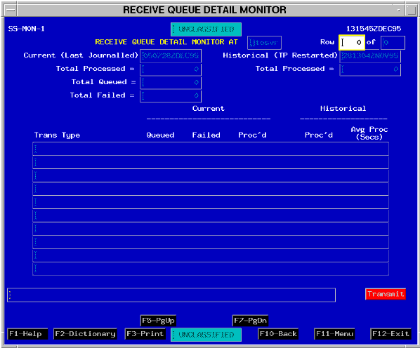
Row. A two part field, the first part displays the number of the row that is displayed on the top line of the transaction details list. The second part displays the total number of rows available.
Note: Ten rows of transactions appear on the window. More transaction types may be available as indicated in the second part of the Row field. Enter a number other than one in the first part of the Row field and transmit to display the desired information in the first row on the window.
Total Processed. Total number of transactions processed (with status "success" or "success with warning") since the Last Journalled date/time.
Total Queued. Total number of transactions waiting to be processed.
Total Failed. Total number of transactions that failed during processing since the Last Journalled date/time.
Note: The sum of the Total Queued and Total Failed fields is the total number of transactions currently in the Receive Queue.
Total Processed. Total number of transactions (successful and failed) since the TP Restarted date/time.
The columns that appear on the bottom of the window contain a list of transaction types and processing details.
Current Queued. The number of transactions waiting to be processed.
Current Failed. The number of transactions that failed during processing since the Last Journalled date/time.
Current Proc'd. The number of transactions processed since the Last Journalled date/time.
Historical Proc'd. The number of transactions processed since the TP Restarted date/time.
Historical Ave Proc (Secs). The average number of seconds required to process each transaction since the TP Restarted date/time.
Note: The standard Message Line is below the transaction details list. This field displays responses to the operator from the system concerning operator input.
| RECEIVE QUEUE SUMMARY | ||
|---|---|---|
| Step | Activity | Anticipated Result |
| 1 | Press <F10> or <POINT AND CLICK (left)> on F10- Back to go back to the previous menu. | Previous menu displays. |
| 2 | On the Monitors tear-off, <POINT AND CLICK (left)> on Receive Queue Summary. | The RECEIVE QUEUE SUMMARY MONITOR window (Fig. 4-3) displays. |
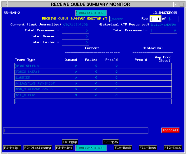
The only field that has different entries is the Transaction Type field. Instead of a six character code displayed, you now see all of the 24 codes grouped into six functional categories.
Now that you know how to get to the windows where you can view the level of activity for the Receive Queue, you should be able to make an estimate of how well the Transaction Processor is operating.
OBJECTIVE. Given a GCCS environment, investigate the local JOPES Database Server's processing performance and status.
The greater the number of transactions, the longer it may take for the TP to get to the ones that you personally entered.
Transaction Failures. The number of failed transactions can also be observed. You again have the options of viewing the Total Failed field, or you can look at the fields displaying the number of failed transactions by functional category or their six character code.
Transaction Processing Time. The system keeps track of how long it takes to actually process a transaction. While there is no "standard" processing time currently established, you could compare the Queued column with the Avg Proc (Secs) column to estimate how long it will take for those transactions currently in the queue to be processed.
Now that you are on speaking terms with the TP and the Receive Queue, the next item on your agenda is the TDS and the Send Queue. The Send Queue navigation also starts from the Monitors tear-off, so you will have to go back to the previous menu.
| RECEIVE QUEUE SUMMARY | ||
|---|---|---|
| 3 | Press <F10> or <POINT AND CLICK (left)> on F10-Back to go back to the previous menu. | Previous menu displays. |
OBJECTIVE. Given a GCCS environment, monitor the JOPES Send Queue activities.
Networked transactions going to other database servers are read from the local Send Queue to determine the appropriate destination.
Send Queue. The Send Queue receives transactions from the client applications. (Refer to Figure 4-1).
The Send Queue monitor keeps track of the number of transactions in the queue waiting to be forwarded and the number of transactions that have already been sent. It keeps track of the 24 types of transactions by the same six character codes used by the TP.
The level of activity in the Send Queue can be monitored using the Send Queue monitoring subsystem.
| SEND QUEUE DETAIL | ||
|---|---|---|
| Step | Activity | Anticipated Result |
| 1 | On the Monitors tear-off, <POINT AND CLICK (left)> on Send Queue Detail. | The SEND QUEUE DETAIL MONITOR window (Fig. 4-4) displays. |
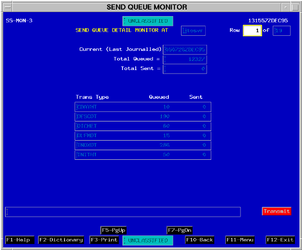
Note: The term "sent" refers to the condition that a transaction has been sent to all other systems. The sum of the Total Queued and the Total Sent fields is the total number of transactions currently in the Send Queue.
Investigate Transaction Distribution Performance. To assess the status of TDS's ability to forward transactions to the other databases, simply check the number of transactions queued and the number of transactions that have been sent.
Now that you are familiar with the Send Queue, it is time to check on the connectivity between the various database servers. You can go back to the Monitors tear-off where you will select the TDS Monitor function next.
| SEND QUEUE DETAIL | ||
|---|---|---|
| 2 | Press <F10> or <POINT AND CLICK (left)> on F10-Back to go back to the previous menu. | Previous menu displays. |
| TDS MONITOR | ||
|---|---|---|
| Step | Activity | Anticipated Result |
| 1 | On the Monitors tear-off, <POINT AND CLICK (left)> on Server Monitor. | The SERVER MONITOR SCREEN window (Fig. 4-5) displays. |
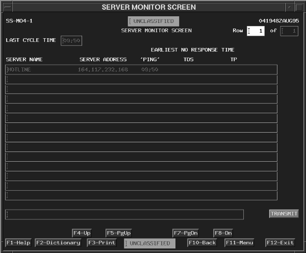 |
The second column (Server Address) will display the servers by specific IP address.
The third column ("Ping"), the fourth column (TDS), and the fifth column (TP) will be either blank or will display a time in hours and minutes.
If time values display in the window, they represent the earliest continuous time that a particular server became inaccessible or a process at that server did not respond.
Blanks displayed in these columns indicate that server connections are established and that the TDS and TP processes are executing.
Note: The information on the screen will be periodically refreshed. The Transmit key can be pressed to immediately query the system and display the current status. The query and response takes approximately five seconds per server if they are accessible and operating, and 10 to 15 seconds per server if a negative response is encountered.
Now that you are comfortable with monitoring the operating status of the various database servers in the network, you can exit this window. The lesson will now describe another monitoring capability, the OPLAN database synchronization monitoring capability.
| TDS MONITOR | ||
|---|---|---|
| 2 | Press <F10> or <POINT AND CLICK (left)> on F10-Back to go back to the previous menu. | Previous menu displays. |
OBJECTIVE. Given a GCCS environment, monitor the synchronization of a distributed OPLAN on the JOPES database and explain how to rectify an out-of-synchronization condition.
Verify OPLAN Synchronization. Use the Plan Management cascade from the GCCS System Services menu to verify OPLAN synchronization.
| VERIFY OPLAN DATABASE SYNCHRONIZATION | ||
|---|---|---|
| Step | Activity | Anticipated Result |
| 1 | On the GCCS SYSTEM SERVICES tear-off, <POINT AND CLICK (left)> on Plan Management. | The Plan Management tear-off menu displays. |
| 2 | <POINT AND CLICK (left)> on Plan Network Status. | A blank Plan Network Status window (similar to Fig. 4-6) displays. |
| 3 | In the PLAN ID field, type "9096m" and press <TAB>. See note. | The completed Plan Network Status window (Fig. 4-6) displays. |
| Note: You may either press the <TAB> key or <POINT AND CLICK (left)> on the Transmit button to execute this function. | ||
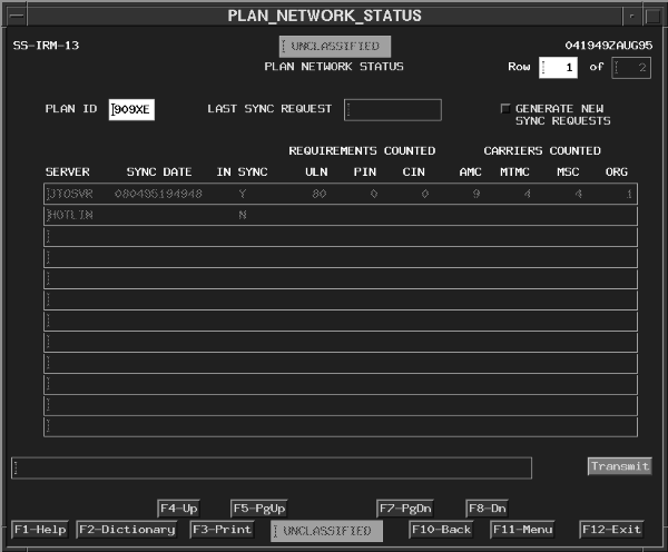 |
The body of the display will contain the synchronization information. The local server will always be displayed on the first line.
The In Sync column displays a Yes/No flag indicating whether or not the remote server reports the same record count as the local server.
The generation of a new sync request will update every site with the most current information.
Note: This could generate a significant number of transactions throughout the network.
Database synchronization has been described and you know how to tell if the database is synchronized. But what can you do if your database is still out-of-sync and all the monitors show that there are no records left to be processed? The next portion of the lesson will show you how to do a partial site recovery for a local site. Keep in mind that a healthy site (one that is fully synchronized) is used to update the site that needs to be recovered. But first, you can exit the window and close the Monitors tear-off.
| VERIFY DATABASE SYNCHRONIZATION | ||
|---|---|---|
| 4 | Press <F10> or <POINT AND CLICK (left)> on F10-Back to go back to the previous menu. | Previous menu displays. |
| 5 | To close the Monitors tear-off, <POINT AND DOUBLE CLICK (left)> on the Window
Menu button  in the upper left corner of the tear-off. in the upper left corner of the tear-off. |
The Monitors tear-off closes. |
| SITE DATA RECOVERY | ||
|---|---|---|
| Step | Activity | Anticipated Result |
| 1 | On the Plan Management tear-off, <POINT AND CLICK (left)> on the Selective Site Data Recovery option. | The SELECTIVE SITE DATA RECOVERY window (Fig. 4-7) displays. |
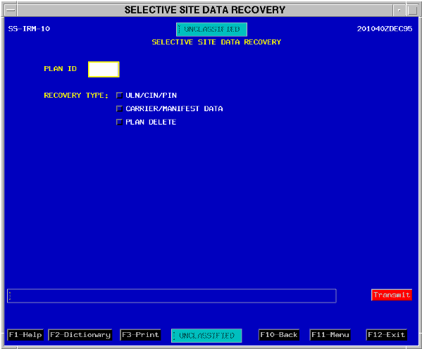
After you enter the Plan ID, the system will check to determine if you have access to the plan. Then you depress one of the Recovery Type toggles to display additional options.
| SITE DATA RECOVERY | ||
|---|---|---|
| 2 | In the PLAN ID field, type "9096m". | Plan ID posts. |
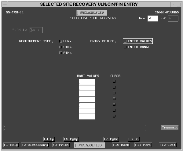
| 3 | <POINT AND CLICK (left)> on the ULN/CIN/PIN toggle. | The SELECTIVE SITE RECOVERY window (similar to Fig. 4-8) displays with just the REQUIREMENT TYPE toggles shown on the window. |
| SITE DATA RECOVERY | ||
|---|---|---|
| 4 | <POINT AND CLICK (left)> on the ULN toggle. | The SELECTIVE SITE RECOVERY window (similar to Fig. 4-8) displays with the ENTRY METHOD toggles added to the window. |
| SITE DATA RECOVERY | ||
|---|---|---|
| 5 | <POINT AND CLICK (left)> on the ENTER VALUES toggle. | The SELECTIVE SITE RECOVERY window (Fig. 4-8) displays with the REQMT VALUES panel added to the window. |
| SITE DATA RECOVERY | ||
|---|---|---|
| 6 | <POINT AND CLICK (left)> on Transmit. | The SELECTIVE SITE RECOVERY window (similar to Fig. 4-9) displays with the DES- TINATION toggles added to the window. |
| 7 | <POINT AND CLICK (left)> on the Specific Sites toggle. | The SELECTIVE SITE RECOVERY window (Fig. 4-9) displays with the ENTER SITE IDENTIFIERS OF SITE TO RECOVER added to the window. |
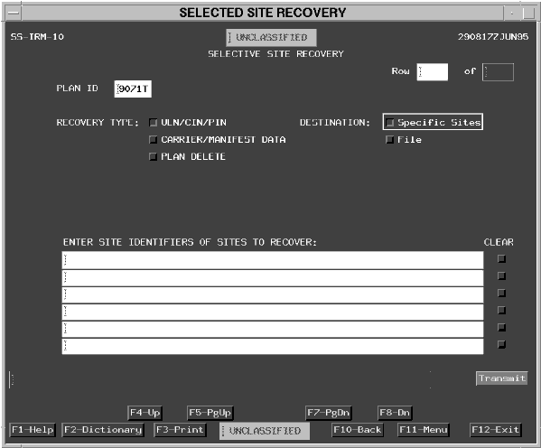
If you had selected the Carrier/Manifest Data toggle on the first Selective Site Recovery window (Fig. 4-7), a different window appears where you enter carrier names for recovery. Again you return back to (Fig. 4-9) to select the file or site(s) to receive the information.
If you initially select the Plan Delete toggle on the first Selective Site Recovery window (Fig. 4-7), no additional options are added to the window. The Plan Delete toggle is used when a networked plan is deleted but does not completely delete from every site around the entire network.
To actually execute the Selective Site Recovery option, you would depress the Transmit button. However, you do not have a direct need to start the recovery process so you can go back to the previous menu.
| SELECTIVE SITE DATA RECOVERY | ||
|---|---|---|
| 8 | Press <F10> or <POINT AND CLICK (left)> on F10-Back to go back to the previous menu. | Previous menu displays. |
OBJECTIVE. From a list of possible answers, select the sequence of events for journalization and the conducting of audits for his/her site's JOPES server.
Personnel Involved. Journalling requires UNIX execute permissions to the Journalling subsystem. The UNIX permissions are granted by making the USERID (user account) a member of the UNIX group responsible for Journalling activities (usually the JADMIN group). The user account and group name are established by the System Administrator.
Each database site must establish procedures to execute and control the journalization process. Procedures will probably vary by site. It could be a Functional Manager responsibility, a System Administrator responsibility, or a Database Administrator responsibility (if one is specifically designated).
Auditing. The Audit Reports subsystem works in conjunction with the journalling function. Reports are generated with data taken from the journalled information.
Personnel Involved. There is one option on the System Services menu that provides access to the JOPES database auditing capability. Everyone who has access to the Systems Services icon has access to the windows that generate the audit reports. No specific functional permission is required to access and execute an audit report. There are some procedural issues that will have to be addressed between the generator of the audit report and the keeper of the journalized information.
Note: These procedural issues are addressed during the generation of an audit report later in this lesson.
OBJECTIVE. Given a GCCS environment, access the window which controls the JOPES journalizing function and explain the options available.
Note: This is the real system! Selected functions are carried out when you select "Transmit." Do not "Transmit" any information on the Journalling subsystem window unless you are the designated individual responsible for accomplishing the Journalization function.
| JOURNALLING SYSTEM | ||
|---|---|---|
| Step | Activity | Anticipated Result |
| 1 | On the GCCS SYSTEM SERVICES tear-off, <POINT AND CLICK (left)> on Journalling. | The JOURNALLING SUBSYSTEM window (Fig. 4-10) displays. |
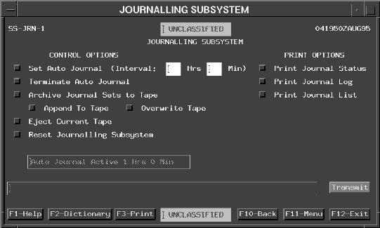 |
If you select the Set Auto Journal toggle, enter an interval in hours and minutes and <POINT AND CLICK (left)> on Transmit. The system will immediately journal and then automatically repeat the operation at the interval specified.
If you select the Terminate Auto Journal toggle and <POINT AND CLICK (left)> on Transmit, the Journalling subsystem will stop automatic journalling after any currently active journalling operation concludes.
The current status of journalling is displayed in a field above the message field. This status can be either "Auto Journal Inactive" or a message indicating the current journalling interval.
Archive to Tape. Four of the toggles on this window control the archiving (and cleaning out) of the information stored in three journal disk files. They are the Archive Journal Sets to Tape, Append to Tape, Overwrite Tape, and Eject Current Tape toggles.
Note: The three journal disk files containing the information obtained from the Receive and Send Queues should periodically be archived to tape in order to conserve disk space. The System Administrator or Database Administrator can access these files from system level to check/verify their size.
Note: The tape drive used by the Journalling subsystem is a default tape drive identified by the System Administrator (SA) during initial installation. The default tape drive can be modified by the SA.
If you select the Archive Journal Sets to Tape and the Overwrite Tape option, then the system will transfer three journal disk files to tape, overwriting all files on that tape.
Eject Current Tape. If you select the Eject Current Tape and <POINT AND CLICK (left)> on Transmit, the tape in the default tape drive is ejected.
Note: As of this writing, there is no tape management system/procedures promulgated. If you save something to a tape, you should make arrangements to put the tape in the tape drive, keep track of what is on that tape, and store it or know where it is stored.
Journal Reports. There are three report options available to the individual responsible for journalling operations. They are the Print Journal Status, Print Journal Log, and Print Journal List options. These three reports print the contents of three of the files that the journalling system uses for processing.
Note: These three files are not the contents of the Receive and Send Queues. They contain information concerning the proper operation and the care and feeding to the Journalling subsystem.
The Journal Log Report (file) records time stamped status messages such as start and stop times as well as error messages recorded during processing.
The Journal List Report (file) lists all the files in the Journal directory.
Reset Journalling Subsystem. The Reset Journalling Subsystem toggle is used when the Journal Log file grows too large or when the Journal List file becomes inconsistent with the actual files in the Journal directory.
Note: If you select the Reset Journalling Subsystem toggle and <POINT AND CLICK (left)> on Transmit, then the Journal Log file is emptied and the Journal List file is updated to the current contents of the Journal directory.
| AUDIT REPORTS SUBSYSTEM | ||
|---|---|---|
| Step | Activity | Anticipated Result |
| 1 | Press <F10> or <POINT AND CLICK (left)> on F10- Back to go back to the previous menu. | Previous menu displays. |
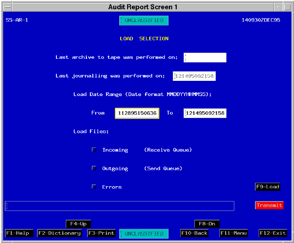
| 2 | On the GCCS SYSTEM SERVICES tear-off, <POINT AND CLICK (left)> on Audit Reports. | The LOAD SELECTION window (Fig. 4-11) displays. |
OBJECTIVE. Given a GCCS environment, conduct a JOPES audit.
Requirement. For your information, OPLAN 9096M contains (and should only contain) Army records. However, there is now an Air Force record in your JOPES database. The ULN is 9BLCK. Your task is to discover who and when that record was added to your OPLAN.
Note: If a transaction has recently occurred and journalization has not yet happened, then auditing of that transaction cannot occur.
The second field reports the last time journalling was performed (database transaction information was transferred from the transaction queues to the journal disk area).
These fields are blank if the Journalling subsystem has been reset and neither activity has occurred since the reset.
The Load Date Range section contains two fields you must complete to access the appropriate transactions. The "To" field defaults to the current date and time. A time frame is specified by entering the earliest time in the From field and the latest time in the To field. The format for entering the date is displayed in the window.
You then specify the source of journalled information that should be loaded. The sources of information correspond to the three journal files that were created by the Journalling subsystem. Any combination of these three files can be loaded. The choices are:
Outgoing -- loads the transactions that were processed by the Transaction Distribution Services in conjunction with the local Send Queue.
Errors -- loads information that was resident in either the Receive or Send Queues about transactions that failed or generated warnings during their application or execution.
Once both the date range and transaction sources to be loaded have been identified, the transactions must be retrieved from either disk and/or tape. The F9-Load button loads the journalling information.
Note: If transactions must be loaded from a tape, then you must coordinate with the individual who has access to those tapes to insert the "appropriate" tape into the "default" tape drive. The "appropriate" tape can be identified by the dates written on the tape label when archiving was accomplished. The "default" tape drive is identified by the System Administrator. In many cases, it will probably be the same one as the one used by the Journalling subsystem.
| AUDIT REPORTS SUBSYSTEM | ||
|---|---|---|
| 3 | <POINT AND CLICK (left)> on the From field. Type {yesterday's date} at 0001Z in the format {MMDDYY000100}. | Date and time post. |
| 4 | In the To field. Type the {date last journalled} from the field above. | Date and time last journalled post. |
| 5 | <POINT AND CLICK (left)> on the Load Files: Incoming (Receive Queue) toggle and the Load Files: Outgoing (Send Queue) toggle. | Both toggles are depressed. |
| 6 | Press <F9> or <POINT AND CLICK (left)> on the F9- Load button. | Load sequence initiates and loading successful message appears. |
Note: If this window is exited and subsequently re-entered, then all previously loaded information is dumped.
| AUDIT REPORTS SUBSYSTEM | ||
|---|---|---|
| 7 | <POINT AND CLICK (left)> on the Transmit Button. | The REPORT SELECTION window (Fig. 4-12) displays. |
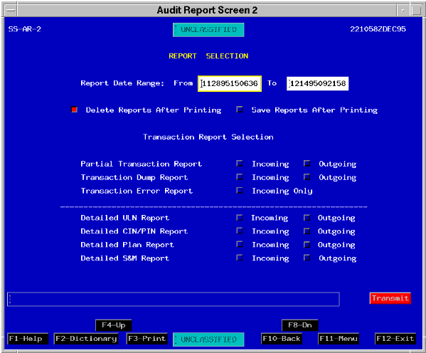
The reports may be printed only, or they may be printed and saved to a file. The default pathname is /h/SM/data/user_files/{userid}. Toggling either of the "after printing" options untoggles the other.
The lower portion of the window allows you to select the type of reports you want. The reports above the separator line are the non-detailed reports, while those below the line are detailed reports.
Note: The detailed reports can be restricted to specific types of information such as Plan Status, ULN, or carrier. You cannot limit the non-detailed reports to specific types of transactions. You cannot request both detailed and non-detailed reports at the same time. You can, however, select any combination of detailed reports or any combination of non-detailed reports. The choice of detailed or non- detailed reports determines the windows that are subsequently displayed.
Note: A separate report is generated for each option (report) selected.
| AUDIT REPORTS SUBSYSTEM | ||
|---|---|---|
| 8 | <POINT AND CLICK (left)> on the Save Reports After Printing toggle. | Depresses the Save Reports After Printing toggle. |
| 9 | <POINT AND CLICK (left)> on the Detailed ULN Report Incoming and Outgoing toggles. | Depresses the Detailed ULN Report toggle. |
| 10 | <POINT AND CLICK (left)> on Transmit. | The DATABASE/USER ID SELECTION window (Fig. 4-13) displays. |
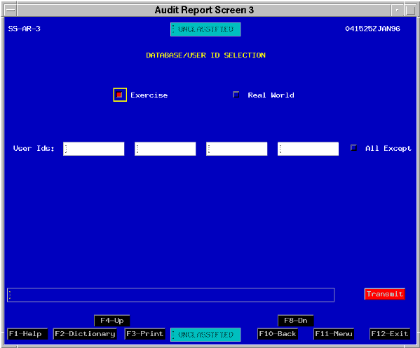
| AUDIT REPORTS SUBSYSTEM | ||
|---|---|---|
| 11 | <POINT AND CLICK (left)> on the Exercise toggle. | Depresses the Exercise toggle. |
| 12 | <POINT AND CLICK (left)> on Transmit. | The REQUIREMENT/CARRIER SELECTION window (Fig. 4-14) displays. |
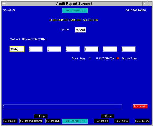
| AUDIT REPORTS SUBSYSTEM | ||
|---|---|---|
| 13 | Type "9096m" in the Oplan field. | 9096M displays in the OPLAN field. |
| 14 | <POINT AND CLICK (left)> on the first ULN field and type "9blck" in the field. | 9BLCK displays in the ULN field. |
| 15 | <POINT AND CLICK (left)> on Transmit. | The REPORT SELECTION window (Fig. 4-12) redisplays. |
| 16 | Press <F10> or <POINT AND CLICK (left)> on the F10- Back button to return to the previous window. | The previous window displays. |
Note: The report will print on the default printer for your workstation as previously configured by the System Administrator.
| AUDIT REPORTS SUBSYSTEM | ||
|---|---|---|
| 17 | Walk, run, or drive to your default printer and review your report. | |
| 18 | Determine who, when, and how ULN 9BLCK was added to your JOPES database. | |
| 19 | Press <F10> or <POINT AND CLICK (left)> on the F10- Back button to return to the previous window. | The previous window displays. |
The next portion of the lesson covers JOPES file transfers.
Overview of Importing and Exporting Data. Figure 4-15 is the big picture for file transfers to include OPLANS, TPFDDs, and reference files.
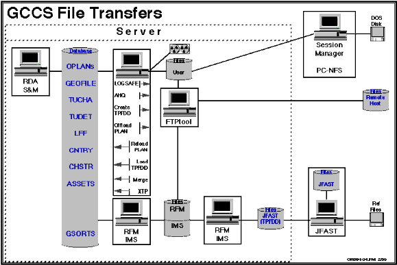
The lesson first describes the System Services functions used to upload and download OPLAN/TPFDD information into and out of the JOPES database. They are the Create TPFDD File, Offload Plan, Reload Plan, Load TPFDD, and Merge options.
That will be followed by a description of three other functions called the Information Management System (IMS), Reference File Manager (RFM), and the File Transfer Protocol (FTPtool) used to transfer TPFDDs and reference files between application files and computer files.
OBJECTIVE. Without references, identify, in specific terms, the method(s) used to export and/or import JOPES OPLANs/TPFDDs.
| CREATE TPFDD FILE | ||
|---|---|---|
| Step | Activity | Anticipated Result |
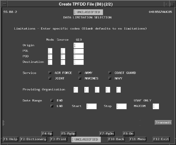
| 1 | From the GCCS SYSTEMS tear-off, <POINT AND CLICK (left)> on Create TPFDD File. | The DATA LIMITATION SELECTION window (Fig. 4-16) displays. |
 |
The window also allows you to specify the offload media and pathname for disks or the device name for local tape drives. To use a tape drive, a blank tape must already be installed in the drive.
The pathname tells the UNIX program where to store the information file within the GCCS file system.
For example, the directory path to your user account is /h/USERS/{USERID} where {USERID} is a variable that represents your USERID. Additional directories, like User_Storage, can be added to the path to provide additional file locations.
You will use the Create TPFDD File option to extract Marine records from an OPLAN and put them on a disk file in your user account.
Requirement. Extract all Marine force and nonunit records from the 900XT OPLAN and store the records on a disk file in your user account's User_Storage directory.
Note: The "X" in 900XT is a placeholder. Your instructor should provide you with the appropriate number or letter to use to replace the "X". For example, for 900XT the "X" is usually the last digit of the current fiscal year.
| CREATE TPFDD FILE | ||
|---|---|---|
| 2 | In the Plan field, type "900xt". | Plan ID posts. |
| 3 | Confirm the Store to: Disk toggle is depressed. | Toggle is depressed. |
| 4 | <POINT AND DOUBLE CLICK (left)> on the Path field and type "/h/USERS/{userid}/User_Storage"; insert your user account's USERID in place of the {USERID} variable. See note. | Disk directory path posts to the field. |
| Note: The directory names are case sensitive (upper/lower) and must be entered as shown. User_Storage is a symbolic link directory that takes the place of a directory string titled Scripts/User_Storage. | ||
| 5 | <POINT AND CLICK (left)> on the Filename field and type "900xt_marines". | Filename posts. |
| CREATE TPFDD FILE | ||
|---|---|---|
| 6 | <POINT AND CLICK (left)> on the Both Force and Non-unit
records toggle.
<POINT AND CLICK (left)> on Transmit. |
Toggle is depressed and the DATA LIMITATION SELECTION window (Fig. 4-17) displays. |
 |
