 |
Publication Date: 17 February 1996
System Version: GCCS 2.1/Update 4
Web Page Created: 20 March 1996
Setup. To accomplish this lesson, you will need GCCS connectivity and access to the JOPES database and JOPES applications (Session Manager, System Services (SS), Requirements Development and Analysis (RDA), Scheduling and Movement (S&M), and Transportation Component Command External System Interface (TCCESI)). Your USERID must have Create (CRT), Update (UPD), and Network Functional Manager (NFM) permissions. Your USERID must also be able to execute the functions in the TCCESI application.
With that in mind, you will begin with how the FM can create a database on the local server using TPFDD or transaction data from several different sources.
OBJECTIVE. Given a JOPES environment, load an exercise, restricted access, local, unclassified OPLAN on the local server.
Tape/Disk or File. The source of your OPLAN or TPFDD, if not already on the JOPES database, will usually come from one of two different locations. The information could be external to the system, that is, on a magnetic tape or a floppy disk stored in a vault or in a safe somewhere. It could also be stored in someone's personal file on the system somewhere, just not in the JOPES database.
It doesn't really make any difference where it is, your task is to get it from its current location into the JOPES database. That is called Loading the Plan.
This option will initialize an OPLAN shell in the database to receive the records.
Reload Plan. The Reload Plan option allows you to reload an OPLAN file.
This option will initialize an OPLAN shell in the database to receive the records.
Requirement. Use the Reload Plan option to reload OPLAN 9096M into the database. OPLAN 9096M contains only Army records and it is the one that you previously offloaded to a file in your user storage area. You will reload it into a new OPLAN (909XT). During the reload process, you will be required to initialize 909XT as an exercise, restricted, local, and unclassified OPLAN.
| RELOAD PLAN | ||
|---|---|---|
| Step | Activity | Anticipated Result |
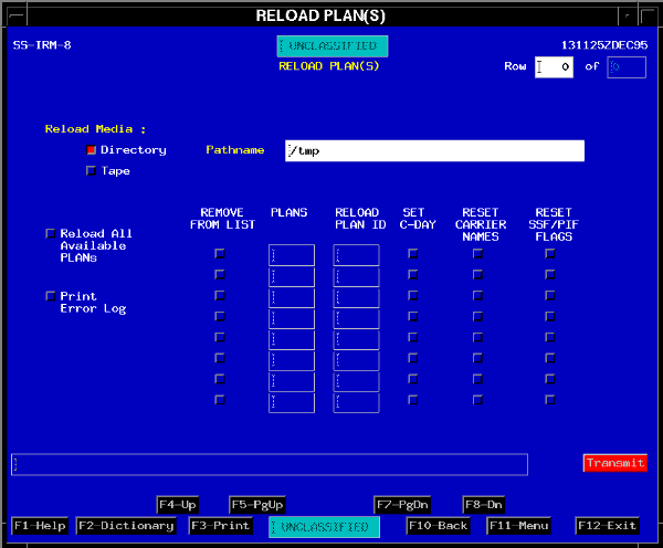
| 1 | From the Plan Management tear-off, <POINT AND CLICK (left)> on Reload Plan. | The RELOAD PLAN(S) window (Fig. 5-1) displays. |
 |
| RELOAD PLAN | ||
|---|---|---|
| 2 | Confirm Directory toggle is depressed. | Toggle is depressed. |
| 3 | <POINT AND DOUBLE CLICK (left)> on the Pathname field and type the path to your user account directory "/h/USERS/{userid}/User_Storage"; insert your user account's USERID in place of the {userid} variable. | Identifies the location on the server where this file is stored. |
| 4 | <POINT AND CLICK (left)> on the Reload All Available PLANS toggle. | An Overwrite and Continuation pop-up displays. |
| 5 | <POINT AND CLICK (left)> on Yes. | All OPLANs in your directory with a .OFF extension to the file number post to the PLANS column. |
| RELOAD PLAN | ||
|---|---|---|
| 6 | <POINT AND CLICK (left)> on the Remove From List toggle for all plans except the plan(s) you wish to reload. | Only the plan(s) you wish to reload remain. |
| 7 | <POINT AND DOUBLE CLICK (left)> in the RELOAD PLAN ID column and type "909xt". | OPLAN ID posts. |
Reset Carrier Names. If the carrier names are reset, the reloaded carrier information will be renamed according to the following convention: the first five characters are retained; followed by the OPLAN ID; followed by a five character sequence number. Duplicate carrier transactions are always rejected because the JOPES database does not allow duplication of carrier names. However, if a carrier's characteristics and itinerary did not change while the OPLAN was stored in the file, the reloaded OPLAN movement requirement records are relinked to the existing carrier's itinerary.
Reset SSF/PIF Flags. If this toggle is selected, then these fields in the database will be set to null.
Print Error Log. If you want a printed report of the errors that occur during the reload, then you would depress this toggle.
| RELOAD PLAN | ||
|---|---|---|
| 8 | <POINT AND CLICK (left)> on Transmit. | Confirmation pop-up displays. |
| 9 | <POINT AND CLICK (left)> on Yes. | The PLAN MAINTENANCE initialize window (Fig. 5-2) displays. |
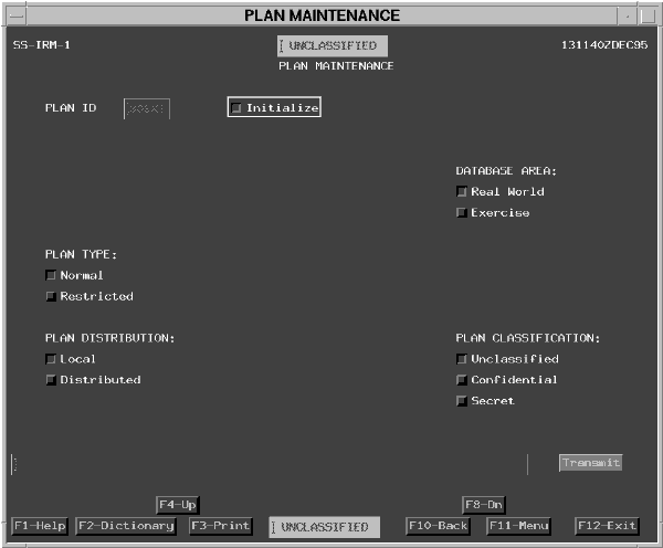 |
Plan Type (Normal/Restricted). There are two types of OPLANs: normal and restricted.
A normal OPLAN is accessible by everyone who has permission to that particular OPLAN number series.
Note: To change a local plan's type, the operator must be the creator, Site FM, or Network FM. To change a distributed plan's type, you must be the creator or Network FM.
| RELOAD PLAN | ||
|---|---|---|
| 10 | <POINT AND CLICK (left)> on the Exercise toggle. | Exercise toggle is depressed. |
| 11 | <POINT AND CLICK (left)> on the Restricted toggle. | Option is marked as selected and an Enter Userids toggle displays. |
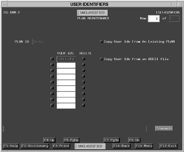
| 12 | <POINT AND CLICK (left)> on the Enter Userids toggle. | Option is marked as selected. The PLAN MAINTENANCE restricted USER IDs menu (Fig. 5-3) displays. |
 |
| RELOAD PLAN | ||
|---|---|---|
| 13 | <POINT AND CLICK (left)> on the second USER
IDS field.
Type the {USERIDs} that you want to have access to your plan. Press <TAB>. <POINT AND CLICK (left)> on Transmit. |
USERIDs posts to the text entry field and the PLAN MAINTENANCE initialize window (Fig. 5-2) redisplays. |
You must have the Network FM permission assigned to distribute (network) OPLANs.
A follow-on window appears to identify site servers to receive the OPLAN.
| RELOAD PLAN | ||
|---|---|---|
| 14 | Confirm the Local and Unclassified toggles are depressed. | Both toggles are red. |
| 15 | <POINT AND CLICK (left)> on Transmit. | Really perform Reload? confirmation pop-up window displays. |
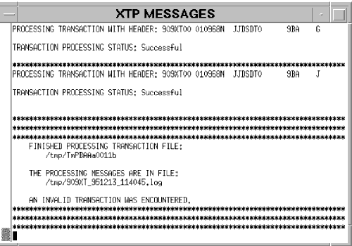
| 16 | <POINT AND CLICK (left)> on Yes. | The RELOAD PLAN(S) window (Fig. 5-2) redisplays in the background and an
XTP MESSAGES window (Fig. 5-4) displays in the foreground.
When the process is finished, a continuation pop-up displays. |
| 17 | <POINT AND CLICK (left)> on Yes. | Both windows remain open with the XTP window in the foreground. |
 |
| RELOAD PLAN | ||
|---|---|---|
| 18 | After processing has completed, <POINT AND DOUBLE CLICK (left)> on the Window Menu button [-] in upper left corner of the XTP Messages window. | The XTP MESSAGES window closes. |
| 19 | <POINT AND CLICK (left)> on the F10-Back button. | The Reload OPLAN window closes. |
OBJECTIVE. Given a JOPES environment, use the System Services capabilities to merge JOPES TPFDD files.
Requirement. Use the Merge TPFDD option to add the Marine TPFDD that you previously uploaded from a floppy disk into a file in your user storage area. Add this Marine TPFDD into your OPLAN (909XT).
| MERGE TPFDD | ||
|---|---|---|
| Step | Activity | Anticipated Result |
| 1 | From the GCCS SYSTEM SERVICES tear-off, <POINT AND CLICK (left)> on Merge TPFDD. | The MERGE REQUIREMENTS window (Fig. 5-5) displays. |
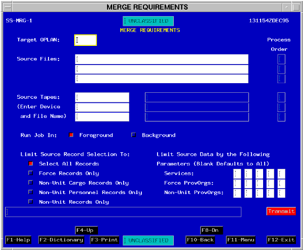 |
To begin the process, you must specify the target OPLAN and up to three TPFDD source files on disk and/or up to three on tape.
You can run the job in the foreground (wait for the job to complete) or background (have the system give you a Process Identification (PID) number).
You can also limit the records selected for the merge.
The merge will not update protected data fields of a locked target OPLAN.
Note: The locked plan's data fields are only protected for the records that have a Schedule Status Flag (SSF) field entry.
| MERGE TPFDD | ||
|---|---|---|
| 2 | Type "909xt" in the TARGET OPLAN: field. | OPLAN number posts |
| 3 | Type "/h/USERS/{userid}/User_Storage/tpfdd.mar" in the SOURCE FILES: field. | /h/USERS/{userid}/User_Storage/tpfdd.mar posts. |
| 4 | If not already toggled, <POINT AND CLICK (left)> on the Run Job In: Foreground toggle. | The Run Job In: Foreground toggle depresses. |
| 5 | If not already toggled, <POINT AND CLICK (left)> on the Select All Records toggle. | The Select All Records toggle depresses. |
| 6 | <POINT AND CLICK (left)> on Transmit. | The Merge Window redisplays with advisory messages in the message line. You should wait for the completion message before continuing. |
| 7 | <POINT AND CLICK (left)> on F11- Menu. | The Merge Requirements Window closes. |
Note: The Merge Report is sent to a file on the server. The default pathname is /h/SM/data/user_files/{userid}/Merge_Report_{date}_{time}. You must access the server via FTPTool or telnet to view the contents of this file.
OBJECTIVE. Given a JOPES environment, execute the process for updating a JOPES OPLAN using transactions from an external source.
Requirement. Use the External Transaction Processor option to add Air Force requirement records (transaction format) that were created and manipulated using an external or unique application, such as DART. This is the other file that you previously loaded from a floppy disk into your user storage area.
| EXTERNAL TRANSACTION PROCESSOR | ||
|---|---|---|
| Step | Activity | Anticipated Result |
| 1 | On the GCCS System Services pull-down, <POINT AND CLICK (left)> on the System Services Utilities option. | System Services Utilities Menu displays. |
| 2 | On the System Services Utilities tear-off, <POINT AND CLICK (left)> on External Transaction Processor. | The EXTERNAL TRANSACTION PROCESSOR window (Fig. 5-6) displays. |
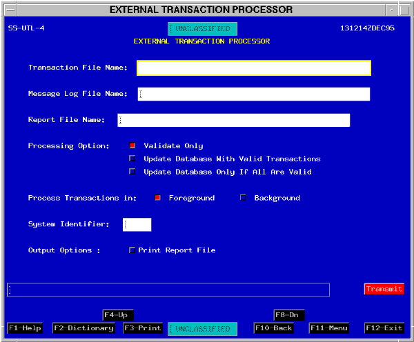 |
Message Log File Name. You enter the full path and file name for the message log that will store information concerning valid and invalid generated transactions. If the file name already exists, then the existing file is overwritten.
Report File Name. You enter the full path and file name for the file that will contain the final summary level report.
Processing Option. The center portion of the window allows the operator to select three different processing options.
Update Database With Valid Transactions. If you select the Update Database with Valid Transactions option, then the XTP will process the transaction file and forward the valid transactions to the JOPES database and the Send Queue. A report on the validity of all of the transactions is generated.
Update Database Only If All Are Valid. If you select the Update Database Only If All Are Valid option, the XTP will process the transaction file. If all the transactions are valid, the transactions are sent to the JOPES database and the Send Queue. If even one transaction is invalid, then no transactions are forwarded for OPLAN update. In either event, a report on the validity of those transactions is generated.
Process Transactions In. The last option on the window allows the operator to execute this process in the foreground or in the background.
Background means that the system will provide a PID number in the message line after you click on Transmit.
System Identifier. This four character field is to be used for future external systems such as COMPESS. Each transaction will be identified by its source system.
Output Options. By clicking on the Print Report File toggle, a hard copy of the report would be generated at your default printer.
| EXTERNAL TRANSACTION PROCESSOR | ||
|---|---|---|
| 3 | Type "/h/USERS/{userid}/User_Storage/909Xt.AF" in the Transaction File Name field. | /h/USERS/{userid}/User_Storage/909Xt.af posts in the Transaction File Name field. |
| 4 | <POINT AND CLICK (left)> on Message Log File Name field. | The Message Log File Name field becomes active. |
| 5 | Type "/h/USERS/{userid}/User_Storage/909Xt.msg." | /h/USERS/{userid}/User_Storage/909Xt.msg posts. |
| 6 | <POINT AND CLICK (left)> on Report File Name field. | The Report Log File Name field becomes active. |
| 7 | Type "/h/USERS/{userid}/User_Storage/909Xt.rpt". | /h/USERS/{userid}/User_Storage/909Xt.rpt posts. |
| 8 | <POINT AND CLICK (left)> on the Processing Option Update Database With Valid Transactions toggle. | The Update Database with Valid Transactions toggle is depressed. |
| 9 | <POINT AND CLICK (left)> on the Process Transaction in Foreground toggle. | The Foreground toggle is depressed. |
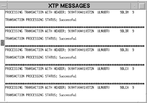
| 10 | <POINT AND CLICK (left)> on Transmit. | An XTP MESSAGES window (Fig. 5-7) displays to provide progress and completion messages as well as the locations of the transaction message and report locations. |
 |
| EXTERNAL TRANSACTION PROCESSOR | ||
|---|---|---|
| 11 | <POINT AND CLICK (left)> on Window Management
button.
<POINT AND CLICK (left)> on the Close option. |
The XTP MESSAGES window closes. |
| 12 | <POINT AND CLICK (left)> on the F11-Menu button. | The EXTERNAL TRANSACTION PROCESSOR window closes. |
OBJECTIVE. Without references, set or reset an OPLAN C-Day and L-Hour, change a plan's type and status, and modify its distribution.
Requirement. Use the Plan Maintenance option to prepare an OPLAN for execution by modifying the plan characteristics. Specifically, set C-Day and L-Hour to 1 January 1996 at 0001Z, modify the Plan Type from Restricted to Normal, confirm that the plan is in an unlocked status, confirm an appropriate classification, and distribute the plan to other sites, as appropriate.
| MODIFY OPLAN CHARACTERISTICS | ||
|---|---|---|
| Step | Activity | Anticipated Result |
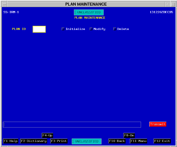
| 1 | On the Plan Management tear-off, <POINT AND CLICK (left)> on the Plan Maintenance option. | The initial PLAN MAINTENANCE window (Fig. 5-8) displays. |
 |
| MODIFY OPLAN CHARACTERISTICS | ||
|---|---|---|
| 2 | Type "909xt" in the PLAN ID field. | 909XT posts in the PLAN ID field. |
| 3 | <POINT AND CLICK (left)> on the Modify toggle. | The Modify toggle depresses and PLAN MAINTENANCE (Modify) options (Fig. 5-9) display. |
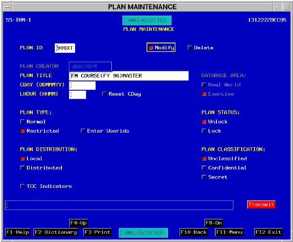 |
In addition to changing what you selected when loading the plan, you can now select other fields/toggles to change the Plan Title, enter or change C-Day and L-Hour, reset C-Day to a blank, lock or unlock the plan, or reset the TCC indicators and movement schedules for AMC, MTMC, MSC, and organic carriers.
C-Day and L-Hour. The C-Day and L-Hour fields allow you to set or change the C-Day and L-Hour for a plan and update the database with the changes. You must be the plan creator or the Site/Network FM to set or change C-Day and L-Hour.
| MODIFY OPLAN CHARACTERISTICS | ||
|---|---|---|
| 4 | <POINT AND CLICK (left)> on the CDAY field. | The CDAY field becomes active. |
| 5 | Type "01jan96." | 01Jan96 posts in the CDAY field. |
| 6 | <POINT AND CLICK (left)> on the LHOUR field. | The LHOUR field becomes active. |
| 7 | Type "0001." | 0001 posts in the LHOUR field. |
Plan Type. The Plan Type controls the accessibility/releasability of the plan. Individuals needing access to a Restricted access plan must all be specifically identified by USERID. A normal access plan is accessible by everyone who has access to that specific series of OPLANs. The plan type can be changed from restricted access to normal access.
| MODIFY OPLAN CHARACTERISTICS | ||
|---|---|---|
| 8 | <POINT AND CLICK (left)> on the PLAN TYPE Normal toggle. | The Normal toggle depresses and the Enter USERIDs option disappears. |
Plan Distribution. Plan Distribution can only be changed from local to distributed by the Network FM.
| MODIFY OPLAN CHARACTERISTICS | ||
|---|---|---|
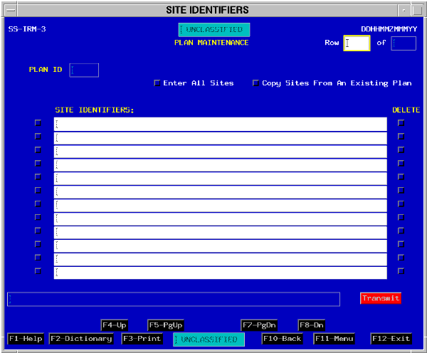
| 9 | <POINT AND CLICK (left)> on the PLAN DISTRIBUTION Distributed toggle. | The Distributed toggle depresses and the Enter Sites toggle displays. |
| 10 | <POINT AND CLICK (left)> on the Enter Sites toggle. | The PLAN MAINTENANCE SITE IDENTIFIERS window (Fig.5-10) displays. |
 |
| MODIFY OPLAN CHARACTERISTICS | ||
|---|---|---|
| 11 | <POINT AND CLICK (left)> on the left toggle of the first row. | The toggle depresses and the first row field is activated. |
| 12 | Type "{site identifier}" in the first row field. | The {site identifier} posts. |
| 13 | <POINT AND CLICK (left)> on Transmit. | The PLAN MAINTENANCE (modify) window (Fig. 5-9) redisplays. |
TCC Indicators. Selecting the TCC Indicators toggle displays a second window to reset TCC indicators for all or selected carrier schedules. The indicators are changed and carrier allocations/manifests are deleted as defined by the selections chosen on the window.
Note: TCC indicators show the Status to the POD as Part(ial) or Full(y) allocated/manifested for each requirement record. These indicators are visible when using the S&M application.
| MODIFY OPLAN CHARACTERISTICS | ||
|---|---|---|
| 14 | <POINT AND CLICK (left)> on Transmit. | The Modify Plan Type Confirmation pop-up displays. |
| 15 | <POINT AND CLICK (left)> on Yes. | The Modify CDAY/LHOUR confirmation pop-up displays. |
| 16 | <POINT AND CLICK (left)> on Yes. | The Modify Distribution pop-up displays. |
| 17 | <POINT AND CLICK (left)> on Yes. | The PLAN MAINTENANCE window (Fig. 5-8) redisplays with an advisory message. |
| MODIFY OPLAN CHARACTERISTICS | ||
|---|---|---|
| 18 | <POINT AND CLICK (left)> on F11- menu. | The PLAN MAINTENANCE window closes. |
OBJECTIVE. Given a random list of the steps in the validation through manifesting process, put them in the proper order.
You will also be exposed to procedures the JPEC could follow and the roles and responsibilities of the Site Validator. Additionally, this lesson covers the effects of this process on the JOPES database, what TPFDD data fields are involved, and the software tools available. It concludes with the use (hands-on) of the TCCESI application software to demonstrate the validation through manifesting process and the characteristics and capabilities of this particular application. You will also be introduced to the JOPES interface with the TCC automated systems.
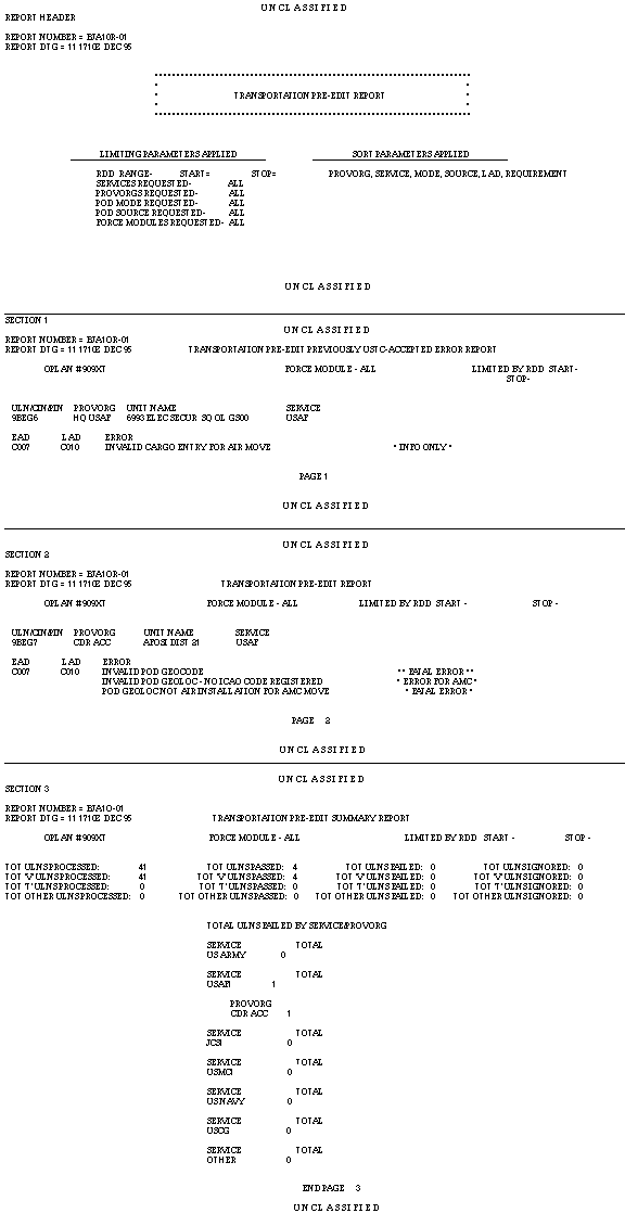
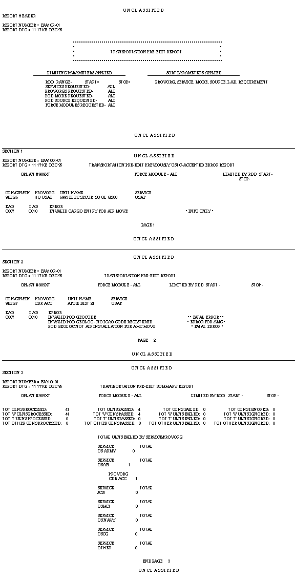
Ensure the Accuracy of the Data Relative to Deploying Forces. The Supported Command ensures an increment of strategic movement requirements; normally, the air validation increment is by the earliest arrival date (EAD) and six days from the current C-Day, while the sealift validation increment is by the latest arrival date (LAD) and for 30 days. The Supported Command verifies that each field that has any transportation significance is complete and accurate. The CINC has a couple of automated tools to assist him, primarily the Transportation Pre-Edit Report and the Logical Errors Report.
Principal Validation Players. The primary JPEC players in the validation process are listed below.
Supported Commander's Components. The supported commander's components work with the Services and other force providers to ensure the proper forces are available to support the dates in the OPLAN.
Supporting Commanders. The supporting commanders provide forces to support the OPLAN.
Force Providers. This group provides forces to support the OPLAN.
Pull Process. The pull process begins with USTRANSCOM recognizing the records that the Supported CINC has identified as ready for scheduling.
Principal Player. USTRANSCOM is the major player in the pull process.
Allocation Process.
Develop Carriers. This step develops carrier names, itineraries, and lift capacities.
Disseminate Schedules. This step adds carrier schedules for specific planned movement requirements into the JOPES database where they are available for all to see.
Principal Players. All three of USTRANSCOM's components have a role in the allocation process.
Automatic Interface. From GDSS, the schedules and any changes to previous airlift scheduling information is passed through GTN into JOPES. The JOPES database is automatically updated.
Automatic Interface. Presently there is no direct interface between SEASTRAT and JOPES. All sealift schedules are hand jammed into JOPES using the S&M application.
MTMC. MTMC gets its movement requirements from USTRANSCOM via an Ad Hoc Query retrieval and puts them into their automated scheduler. The schedules (trucks and trains) can then be put into JOPES via the S&M application.
Automatic Interface. Presently there is no direct interface between STRADS and JOPES. All MTMC derived information must be manually entered into JOPES.
Manifesting Process. Many organizations have a role in the manifesting process.
Plan Onward Movement. The Supported Commander can use the manifest to plan the onward movement of his passengers and cargo and determine feasible unit closure dates.
Principal Players. The following are major players in the manifesting process.
Supported Commander. The supported commander has a vital interest in the arrival of forces in the theater. He/She must plan onward movement from POD to destination and employ those forces within the concept of operations.
USTRANSCOM. USTRANSCOM is interested in the manifesting process for two reasons: to ensure sufficient lift has been allocated to meet the CINC's actual requirements, and to answer intransit visibility questions.
OBJECTIVE. Given a list of the possible effects of the validation through manifesting process on the JOPES database, identify those that are true.
Unlocked. From a software point of view, if the OPLAN is left in an unlocked status, then immediate or uncoordinated changes can be made by anyone with "update" permissions. Procedurally, users should only change the specific fields for which they are responsible.
Effect on the database.
The RDA Main Menu Window will show a Status of Locked or Unlocked.
Note: An OPLAN's status is also visible on the RDA OPLAN Summary Window.
Strategic leg info (time, location, mode, and source).
Identifies the record's current scheduled status.
Valid Entries.
T - TRANSCOM Accepted. USTRANSCOM provides its components the validated supported CINC movement requirements via the USTC Requirements Pull Menu option. This option also has a built-in edit check. The edit checks this increment of records to make sure no "fatal" errors (errors which preclude TCC scheduling) have been introduced since validation. The system assigns a "T" (replaces the "V") to ULNs passing the edit (accepted for movement), and a "Pull file" is created.
A - Allocated. Requirements that are allocated (planned) against scheduled missions are system assigned with an "A" (replaces the "T").
B - Both Allocated and Manifested. If the ULN has been allocated, then upon manifesting, the system generates a "B" flag to replace the "A."
M - Manifested. If ULNs are manifested on a carrier but have not been through the allocation process, then the SSF will be changed to an "M" (manifested without allocation). If the record has not even been validated, it will also get an "N" as a PIF code.
Z - Manifested, but Some Data Fields may be Changed (Required Passengers/Cargo). If transportation significant changes need to be made to allocated "A" and/or manifested "M" records, then the SSF code must be manually changed to a "Z." This unlocks the quantity fields so users can correct those fields after allocation/manifesting (even in a locked OPLAN). USTRANSCOM is the only agency that can enter the "Z."
Space/Other. There is no scheduling status associated with this record.
Problem Indicator Flags.
Valid Entries.
C - Manually entered code by the supported CINC to allow modification of the "quantities" field of previously validated ULNs.
P - Manually entered code indicating transportation problem identified by AMC.
M - Manually entered code indicating that the SPOE and/or SPOD can be or has been changed by MSC.
X - Manually entered code indicating transportation problem identified by USTRANSCOM.
N - Machine generated code indicating requirement was manifested before validation.
Space/Other - No problems associated with this record.
Data Flag Last Set Date. The Data Flag Last Set Date shows the latest change date for the SSF or PIF.
Now that you are familiar with the validation through manifesting process and the SSFs, PIFs, and Data Flag Last Set Date fields, you will turn your attention to the primary application that supports the process and effects the flag changes.
OBJECTIVE. Given an operational JOPES environment, use the validation through manifesting supporting software contained in the TCC External System Interface application.
Note: There are six options that are available from this window, however, not all options are always available. For example, of the options listed below, the TCC Problem Indicator Flag Override option does not appear on this window. Only those options available to you will be displayed. The options displayed are controlled by your USERID. In this specific instance, your USERID begins with JD which is not the first two letters of either an AMC, MTMC, or MSC USERID.
Supported CINC Status Flag Override. This function allows the supported command to "invalidate" any previously validated ULNs. This will set the SSF to a space on the database or set the PIF to a "C" which allows the quantities fields to be modified.
Reports and Utilities. The Reports and Utilities function provides a limited reports capability and some database management capability.
USTC Requirements Pull. This function allows USTRANSCOM to pull ULNs that are flagged as "Validated."
TCC Problem Indicator Flag Override. This function allows an AMC user to identify a ULN as having a problem that should be solved prior to scheduling. It also provides MSC the ability to set the PIF to an "M" which allows the SPOE and/or SPOD fields to be changed.
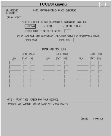
USTC Status/Problem Flags Override. This function allows a USTRANSCOM user to set the SSF and/or PIF for a specified ULN, FM, or OPLAN.
Now that you are familiar with the validation through manifesting process, the SSFs and PIFs, and the agencies who have various responsibilities for setting those flags, please complete the following short practical exercise.
Requirement. The Supported Command has locked the OPLAN. However, after the command has validated a ULN for movement and USTRANSCOM initiated a USTC Requirements Pull, the situation in the AOR changed. The commander now wants an A-10 unit moved up in the flow (it has not been validated) to replace a validated Hawk unit. The Hawk unit will be delayed approximately 30 days.
| PRACTICAL EXERCISE - SSF/PIF CHANGES | ||||
|---|---|---|---|---|
| Step | Problem | Action | Action | Action |
| Given the situation, determine which flags need to be changed, who can change them, and what subsystem would be used? | What Flag needs to be changed? | Who does the change? | What Menu Option? | |
| 5.1 | Invalidate the Hawk unit. | Remove "_" from Hawk ULN | ||
| 5.2 | Validate the A-10 unit. | Add "_" to A-10 ULN | ||
| 5.3 | Pull the A-10 unit. | Add "_" to A-10 ULN | ||
Site Validator Functional Permission. In Version 2.1, these permissions are granted by the SA at system level. In a future version, the granting of this permission is migrating to the FM via the Permissions Window of the SS application.
To be able to execute the specific USTC or TCC options, the first two characters of the users' USERID must reflect a USTRANSCOM or TCC user. All permission checks are performed by the system before the user is allowed into the specified option.
Requirement. The supported command staff has created a TPFDD to support a deployment of forces. An Execute Order has been received and you (the Supported CINC Site Validator) are the individual responsible for validating the movement requirements. Coordination with USTRANSCOM and the JNOCC has been accomplished. USTRANSCOM is expecting you to validate the first six days of airlift movement requirements to be followed by a daily verification cycle. You have already coordinated with your components and have been assured the data for the first six days of airlift requirements is accurate.
| OPLAN LOCKING/UNLOCKING RESTRICTIONS | |||
|---|---|---|---|
| Plan Type | Distribution | Action | User |
| Normal or Restricted Access Plan | Distributed | To Lock | Access and be Network FM |
| To Unlock | |||
| Normal or Restricted Access Plan | Local | To Lock | Plan Creator or Access and be Site FM |
| To Unlock | |||
| CHANGE OPLAN STATUS TO LOCKED | ||
|---|---|---|
| Step | Activity | Anticipated Results |
| 1 | From the System Services Plan Management Menu, <POINT AND CLICK (left)> on the Plan Maintenance. | The PLAN MAINTENANCE window (Fig. 5-8) redisplays. |
| 2 | Type "909xt" in the PLAN ID block. <POINT AND CLICK (left)> on Modify. |
Plan Maintenance (Modify) Options window (Fig. 5-9) redisplays. |
| 3 | <POINT AND CLICK (left)> on Lock in the Plan Status Section. <POINT AND CLICK (left)> on Transmit. | Plan Status Modification Verification Pop-Up (Fig. 5-11) displays. |
 |
| CHANGE OPLAN STATUS TO LOCKED | ||
|---|---|---|
| 4 | <POINT AND CLICK (left)> on F6-YES. | Plan Maintenance Window with an advisory message in the message line (Fig. 5-8) redisplays. |
| 5 | <POINT AND CLICK (left)> on F12 - Exit. | Confirmation Pop-up displays. |
| 6 | <POINT AND CLICK (left)> on Yes. | User exits all SS windows and returns to the JNAV Window. |
Force Module Creation. To initiate that process, in order to use the TCCESI application, you must first put the specific records you wish to validate in a force module. The creation of that force module and the identification of the records to put in that force module can be done using RDA.
| CREATE FORCE MODULE | ||
|---|---|---|
| Step | Activity | Anticipated Result |
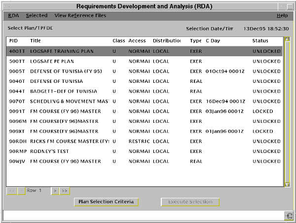
| 1 | From the JNAV Window, <POINT AND CLICK (left)> on the RDA Start button. |
The REQUIREMENTS DEVELOPMENT AND ANALYSIS (RDA) Main Menu window (Fig. 5-12) displays. |
 |
| CREATE FORCE MODULE | ||
|---|---|---|
| 2 | <POINT AND CLICK (left)> on the line containing 909XT. | The line for Plan 909XT is highlighted. |
| 3 | <POINT AND CLICK (left)> on Selected. | The Selected pull-down menu displays. |
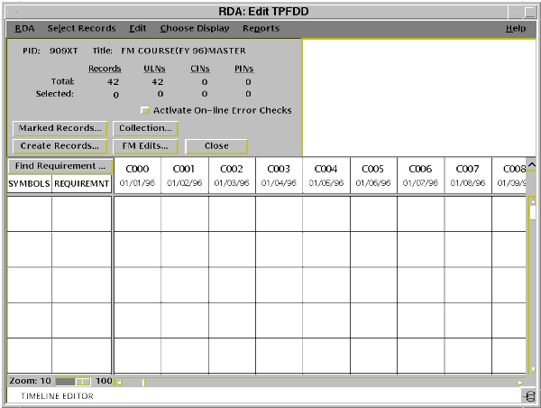
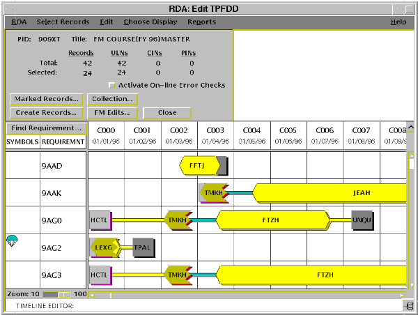
| 4 | <POINT AND CLICK (left)> on the Edit TPFDD. | The RDA:Edit TPFDD window (Fig. 5-13) displays. |
 |
| CREATE FORCE MODULE | ||
|---|---|---|
| 5 | <POINT AND CLICK (left)> on Select Records. | The Select Records pull-down menu displays with the query selection options. |
| 6 | <POINT AND CLICK (left)> on User Defined Queries... | The User Defined Queries Window displays with the names of any previously saved queries. |
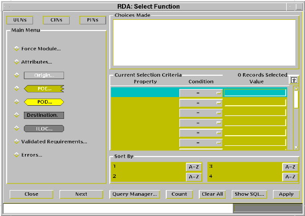
| 7 | <POINT AND CLICK (left)> on the Create New Query button. | The RDA:Select Function window (Fig. 5-14) displays. |
 |
| CREATE FORCE MODULE | ||
|---|---|---|
| 8 | <POINT AND CLICK (left)> on the POD button. | The POD menu displays. |
| 9 | <POINT AND CLICK (left)> on the EAD button. | The enter text box displays and POD - EAD displays in the Current Selection Criteria Property box. |
| 10 | Type "5".
<POINT AND CLICK (left)> on the Accept button. |
5 posts to the value field and the Select Function Main Menu redisplays. |
| 11 | <POINT AND CLICK (left)> on the Condition button. | The Conditions Menu displays. |
| 12 | <POINT AND CLICK (left)> on the less than (<) option. | The < option is selected. |
| 13 | <POINT AND CLICK (left)> on the POD button. | The POD Menu displays. |
| 14 | <POINT AND CLICK (left)> on the Mode/Source button. | The Mode/Source menu displays and POD - Mode/Source posts in the property box. |
| 15 | <POINT AND CLICK (left)> on the A - BY AIR field. | The A - BY AIR field highlights. |
| 16 | <POINT AND CLICK (left)> on the Accept button. | The identified mode/source codes post to the Current Selection Criteria fields. |
| 17 | <POINT AND CLICK (left)> on the Apply button. | The number of records selected posts. |
| 18 | <POINT AND CLICK (left)> on the Close button. | The RDA:Select Function closes and the RDA: Edit TPFDD window (Fig. 5-15) displays with the appropriate collection of records. |
 |
| CREATE FORCE MODULE | ||
|---|---|---|
| 19 | <POINT AND CLICK (left)> on the FM Edits... button. | The RDA:FM Edits Menu displays. |
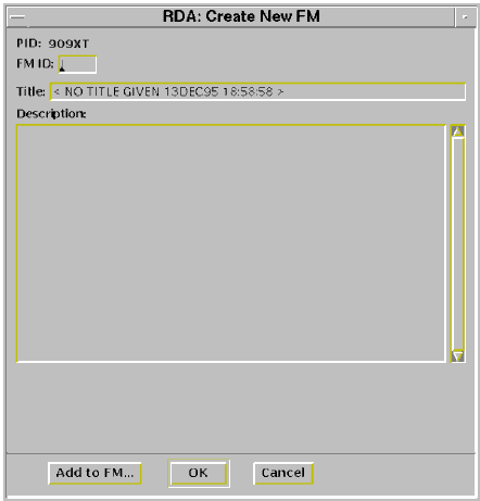
| 20 | <POINT AND CLICK (left)> on the Create New FM... option. | The RDA:Create New FM box (Fig. 5-16 displays. |
 |
| CREATE FORCE MODULE | ||
|---|---|---|
| 21 | Type "9a1" in the FM ID field.
|
The typed entries post to the appropriate fields. |
| 22 | <POINT AND CLICK (left)> on the Add to FM... button. | The RDA:Add to FM Menu displays. |
| 23 | <POINT AND CLICK (left)> on the Collection button. | The confirmation Announcement pop-up displays. |
| 24 | <POINT AND CLICK (left)> on the OK button. | The RDA:Add to FM window closes with the RDA:FM Edits window active. |
| 25 | <POINT AND CLICK (left)> on the Close button. | The RDA:FM Edits menu window closes and the RDA:Edit TPFDD window with the collection (Fig. 5-15) displays. |
Note: Iconify the two RDA windows.
| CREATE FORCE MODULE | ||
|---|---|---|
| 26 | <POINT AND CLICK (left)> on the RDA TPFDD Editor Iconify button. | The RDA:TPFDD Editor window iconifies. |
| 27 | <POINT AND CLICK (left)> on the RDA Iconify button. | The RDA window iconifies. |
| SUPPORTED CINC VALIDATION | ||
|---|---|---|
| Step | Activity | Anticipated Result |
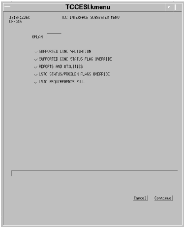
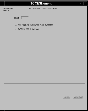
| 1 | From the JNAV window, <POINT AND CLICK (left)> on the TCCESI Start button. | TCC INTERFACE SUBSYSTEM Menu window (Fig. 5-17) displays. |
 |
| SUPPORTED CINC VALIDATION | ||
|---|---|---|
| 2 | <POINT AND CLICK (left)> on the OPLAN block and type "909xt". | 909XT posts to the block and becomes the active OPLAN. |
| 3 | <POINT AND CLICK (left)> on the Supported CINC Validation toggle. | Supported CINC Validation toggle depresses. |
| 4 | <POINT AND CLICK (left)> on the Continue button. | SUPPORTED CINC VALIDATION window (Fig. 5-18) displays. |
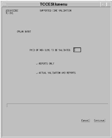 |
Note: All reports generated by the TCCESI application will be in the landscape format and will be automatically printed at your default printer.
The second report that is generated is the Plan Compare Report, which is identical to the RDA Plan Compare and the Reports application PID Comparison reports. This report will include all records with an "A," "T," or a "V" in the SSF field and displays everything that has changed since the last validation cycle.
Actual Validation and Reports: the validator can produce those same reports, mentioned above, (by default, a copy is always printed at USTRANSCOM) as well as mark the records in that force module as having passed (SSF Code - V) or failed (PIF Code - E) the Transportation Pre-Edit check.
The execution of this option also creates seven empty TPFDD files in pathname /h/data/local/esiflatfiles/validate/{OPLAN}/RQMNT01 through RQMNT07 and runs a System Services Create a TPFDD option in the background. The records that were marked with a "V" in the SSF field are copied to the first TPFDD file. The next time, and all subsequent times that a force module is validated, the Transportation Pre-Edit Report is generated, records are marked with a "V" in the SSF field or an "E" in the PIF field, a Create a TPFDD option copies all records in the database with a "V", "T", or an "A" entry in the SSF field to the next TPFDD file, and a Plan Compare Report is generated.
The maximum number of TPFDD files created is seven. When the Supported CINC Validation option is executed for the eighth time, it will overwrite the first TPFDD file. The ninth time will overwrite the second, and so forth.
Note: When the Reports Only option is executed, the records in the force module and those with a "V", "T" or an "A" in the SSF are put into a temporary TPFDD and the Plan Compare Report is generated. After that report is generated, the temporary TPFDD file is deleted. When the Actual Validation and Reports option is executed, the seven permanent TPFDD files are used.
| SUPPORTED CINC VALIDATION | ||
|---|---|---|
| 5 | Type "9a1" in FMID of New ULNs to be Validated. | 9A1 posts to the FM Field. |
| 6 | <POINT AND CLICK (left)> on Actual Validation and Reports toggle. | The Actual Validation and Reports toggle depresses. |
| 7 | <POINT AND CLICK (left)> on Continue. | VERIFY FMID ENTRY window (Fig. 5-19) displays. |
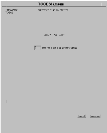 |
| SUPPORTED CINC VALIDATION | ||
|---|---|---|
| 8 | Type "9a1" in REENTER FMID FOR VERIFICATION field. | 9A1 posts to the FM field. |
| 9 | <POINT AND CLICK (left)> on Continue. | Completion advisory message appears in the message line. |
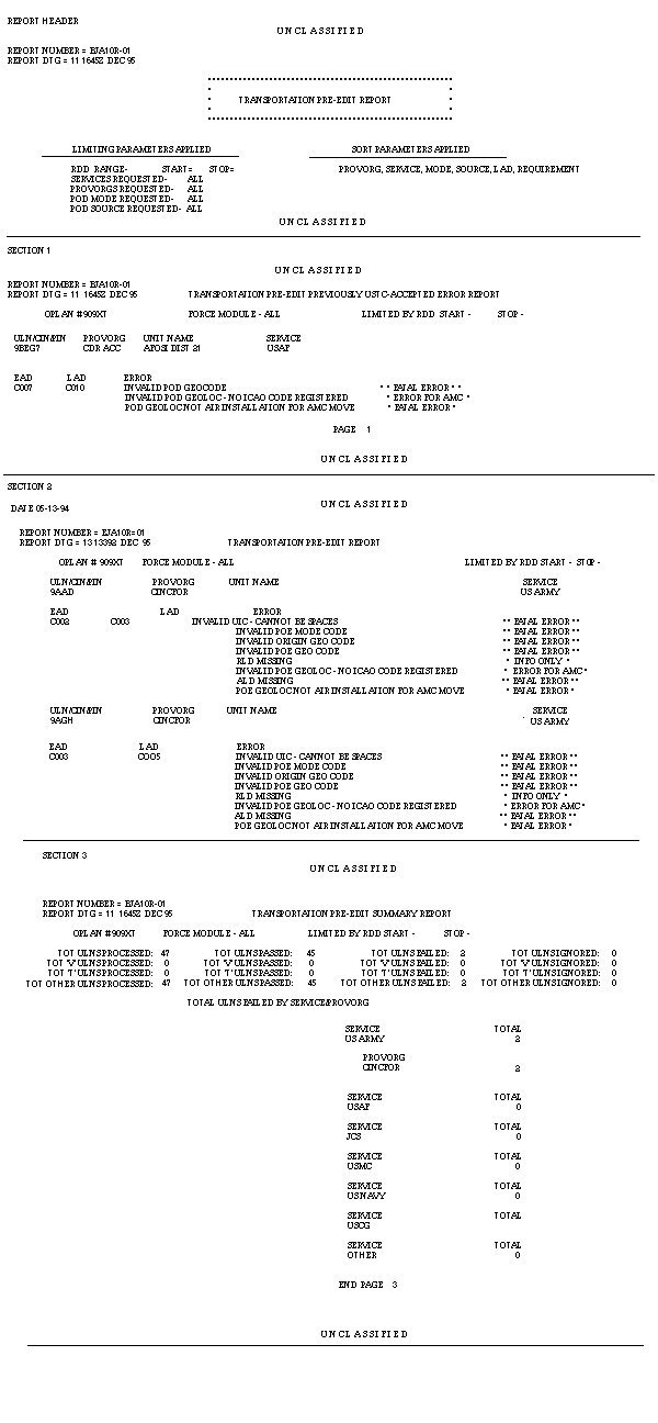 |
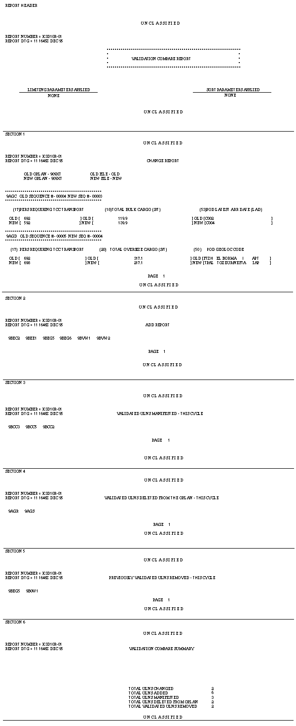 |
| SUPPORTED CINC VALIDATION | ||
|---|---|---|
| 10 | If the advisory message was successful, <POINT AND CLICK (left)> on Cancel. | The Supported CINC Validation Window closes and the TCC Interface Subsystem Menu (Fig. 5-17) redisplays. |
| REVIEW OF SSF AND PIF FIELDS | ||
|---|---|---|
| Step | Activity | Anticipated Result |
| 1 | <POINT AND DOUBLE CLICK (left)> on the RDA:Edit TPFDD Icon. | RDA:Edit TPFDD Window opens. |
| 2 | <POINT AND CLICK (right)> on ULN 9AAD. | RDA:Choose an Operation Menu displays. |
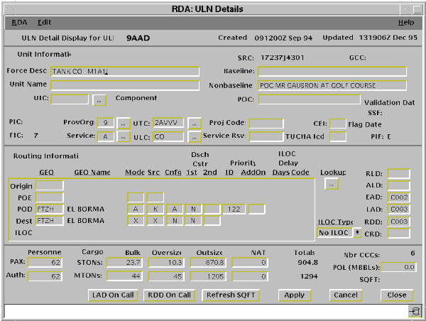
| 3 | <POINT AND CLICK (left)> on the Details... button. | The RDA:ULN Details window for ULN 9AAD (Fig. 5-22) displays. |
 |
| REVIEW OF SSF AND PIF FIELDS | ||
|---|---|---|
| 4 | <POINT AND CLICK (left)> on the Cancel button. | The RDA:ULN Details window closes. |
| 5 | <POINT AND CLICK (right)> on any ULN except 9AAD and 9AGH. | RDA:Choose an Operation Menu displays. |
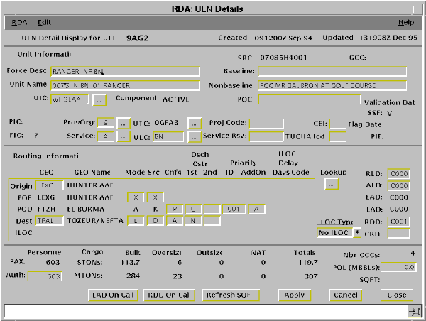
| 6 | <POINT AND CLICK (left)> on the Details... button. | The RDA:ULN Details window for ULN {xxxx} (Fig. 5-23) displays. |
 |
Note: Two records (9AAD and 9AGH) have an "E" in the PIF field while the rest of the records in force module 9A1 have a V in the SSF field. The records with an "E" in the PIF field are not ready to be passed to USTRANSCOM for scheduling. The Supported Command should contact the Army component (the two are Army records) and ensure they coordinate with FORSCOM to complete the sourcing of those records. After the two records have been repaired, the Supported CINC Validation option of the TCCESI application must be run to validate those two records. If the two records are critical to the operation, then those records should be repaired now and the validation rerun. If the two records can wait until the next time that validation will be executed (our scenario says every 24 hours), they can be added to the next increment.
Requirement. You have contacted your Army component personnel to inform them about the two records requiring repair and they are taking it for action. In the course of your conversation, they indicate that they want to change the EADs to two other records (ULNs 9AGD and 9AGE) that have already been validated. However, the OPLAN is locked and that is one of the protected fields. You concur with the need to change these EADs and will modify the two records to allow your Army component to modify those records.
Add a "C" to the PIF Field. This is also done using the Supported CINC Status Flag Override option on the TCCESI Menu. By adding the "C", the transportationally significant fields that were protected for that particular record will become subject to modification. It must be remembered that when the "C" is added, that record is still validated and USTRANSCOM will pull that record and perhaps/maybe begin the scheduling process. After correcting the record, USTRANSCOM must be notified to start/continue scheduling this ULN. In this instance USTRANSCOM would remove the "C" from the PIF field.
| SUPPORTED CINC STATUS FLAG OVERRIDE | ||
|---|---|---|
| Step | Activity | Anticipated Result |
| 1 | <POINT AND CLICK (left)> on the Supported CINC Status Flag Override toggle. | The Supported CINC Flag Override toggle depresses. |
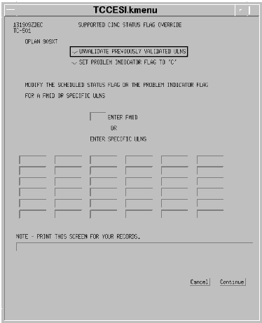
| 2 | <POINT AND CLICK (left)> on the Continue button. | The Supported CINC Status Flag Override window (Fig. 5-24) displays. |
 |
Note. As of Version 2.1, the ability of the TCCESI application to generate a "C" in the PIF is operational, however the Oracle database has not yet been modified to accept a "C" as a valid entry.
| SUPPORTED CINC STATUS FLAG OVERRIDE | ||
|---|---|---|
| 3 | <POINT AND CLICK (left)> on the UNVALIDATE PREVIOUSLY VALIDATED ULNs toggle. | The UNVALIDATE PREVIOUSLY VALIDATED ULNs toggle depresses. |
| 4 | <POINT AND CLICK (left)> on the first ULN field and type "9agd". | ULN 9AGD posts to the field. |
| 5 | <POINT AND CLICK (left)> on the next ULN field and type "9age". | ULN 9AGE posts to the field. |
| 6 | <POINT AND CLICK (left)> on Continue. | A Transaction Queued; System load may cause delays message appears in the message line. |
If you had used the force module option in lieu of the ULN option, then you would have gotten an FMID confirmation window after pointing and clicking on the Continue button.
Note. Now that these records have been unvalidated, the Army component can manipulate the fields that had previously been protected. After the EADs have been changed, the supported command is faced with the same decision faced earlier when the two earlier records failed the transportation pre-edit check. Are the units represented by these two records important enough to the Concept of Operations to accomplish the Supported CINC Validation process again or can they wait until the next normal (in our scenario - daily) validation cycle?
| SUPPORTED CINC STATUS FLAG OVERRIDE | ||
|---|---|---|
| 7 | <POINT AND CLICK (left)> on Cancel. | The Supported CINC Status Flag Override window closes and the TCC Interface Subsystem Menu (Fig. 5-17) redisplays. |
Requirement. You are now one of the individuals at USTRANSCOM who has Site Validator permissions. You have been notified (either by a message (IRC, Newsgroup, or Autodin), phone call, or by looking at the OPLAN database) by the supported command that the first validation increment has been accomplished and the records have been so marked. As the USTRANSCOM Site Validator, you must pull those requirements, verify their transportation accuracy, and pass them to the TCCs for scheduling lift.
| USTC REQUIREMENTS PULL | ||
|---|---|---|
| Step | Activity | Anticipated Result |
| 1 | Insure 909XT is in the OPLAN field and <POINT AND CLICK (left)> on the USTC Requirements Pull toggle. | The USTC Requirements Pull toggle depresses. |
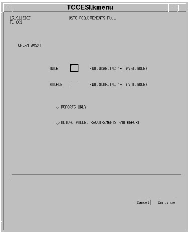
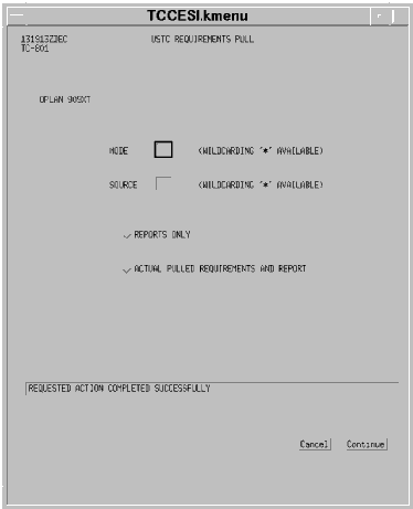
| 2 | <POINT AND CLICK (left)> on the Continue button. | The USTC Requirements Pull window (Fig. 5-25) displays. |
 |
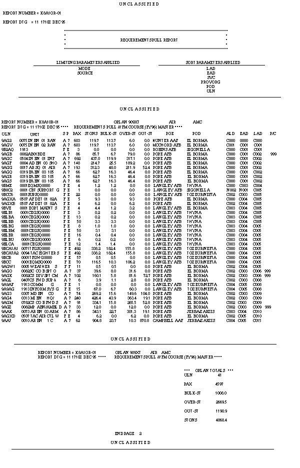
The identified ULNs are edited via the Transportation Pre-Edit to ensure they contain no errors that would preclude TCC scheduling. Any ULNs passing the Pre-edit will be written to a Pull File (also located at pathname /h/data/local/esiflatfiles/validate/{OPLAN}/{MS}PULL) accomplished by an SS Create a TPFDD option that runs in the background. These ULNs will be displayed on the Pull Report. Any ULNs passing the Transportation Pre-Edit and have the identified mode and source for their preferred routing to the POD will be flagged as "Pulled by USTRANSCOM" in the SSF field.
The site validator may execute this function with a "Reports Only" or an "Actual Pulled Requirements and Reports" option. The "Reports Only" option will produce the Transportation Pre-Edit Report and the Pull Report; however, no ULNs will be flagged with a "T." If the user chooses the "Actual Pulled Requirements and Reports" option, any ULNs failing the Pre-Edit Check will be flagged as an error. ULNs passing the Pre- Edit Check will be pulled, and both reports will be produced.
| USTC REQUIREMENTS PULL | ||
|---|---|---|
| 3 | Type "a" in the Mode field. | A posts in the field. |
| 4 | <POINT AND CLICK (left)> on the Source field. | The Source field becomes active. |
| 5 | Type "k" in the Source field. | K posts in the field. |
| 6 | <POINT AND CLICK (left)> on the Actual Pulled Requirements and Report toggle. | The Actual Pulled Requirements and Report toggle depresses. |
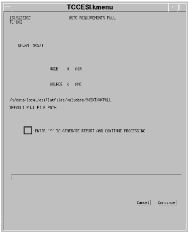
| 7 | <POINT AND CLICK (left)> on the Continue button. | The USTC REQUIREMENTS PULL confirmation window (Fig. 5-26) displays. |
 |
| USTC REQUIREMENTS PULL | ||
|---|---|---|
| 8 | <POINT AND CLICK (left)> on the Enter Y field. | The field becomes active. |
| 9 | Type "y" in the Enter Y field. | Y posts in the field. |
| 10 | <POINT AND CLICK (left)> on the Continue button. | The USTC REQUIREMENTS PULL window with an action advisory message in the message window (Fig. 5-27) displays. |
 |
USTRANSCOM CAT (Site Validator) personnel review these reports to ensure the records are transportationally valid prior to passing them on to the TCCs for scheduling.
| USTC REQUIREMENTS PULL | ||
|---|---|---|
| 11 | If the action advisory message was "successful," <POINT AND CLICK (left)> on the Cancel button. | The TCC Interface Subsystem Menu (Fig. 5-17) redisplays. |
 |
 |
USTRANSCOM Passes Requirements to Components. After the difficulties (if any) have been resolved, USTRANSCOM will pass the requirements to the TCCs for scheduling actions. AMC will be notified of the pathname that contains the requirements ready for strategic air movement. AMC could then use the FTPTool application or FTP at the UNIX prompt to transfer that file to the AMC Host. Personnel at AMC could use the ADANS software to generate aircraft schedules to be pushed into GDSS which is AMC's command and control system.
MTMC and MSC will also be notified that the supported command has verified an increment of requirements, USTRANSCOM has checked them, and they are ready for scheduling. MTMC and MSC then pull hard copy requirements from the JOPES database for the increment of requirements that have been validated. MTMC and MSC then manually enter schedules with those requirements.
After the TCCs have evaluated the movement requirements and generated lift schedules to move those requirements, the information will be entered into JOPES, which is the allocation process.
MTMC. MTMC can use STRADS to begin the scheduling process, but must manually adjust those schedules for them to be usable. As a reminder, there is currently no automated interface between STRADS and JOPES. All MTMC generated information is entered manually in JOPES via the S&M application. When MTMC manually enters schedules (trucks, trains, etc.) into JOPES, the SSF will change to "A" (allocated).
MSC. MSC can use the SEASTRAT to do gross planning, but must also make manual adjustments to obtain useable scheduling information. Its command and control system, Joint Visually Integrated Display System (JVIDS), does not interface with JOPES either. All MSC generated information is manually entered into JOPES; again the SSF will change to "A" (allocated).
AMC is now in the process of generating several schedules and is entering them in their command and control system (GDSS), which, in turn, feeds that information into the JOPES system via GTN. Those schedules, which were allocated to specific ULNs, will change the SSF from "T" (pulled) to "A" (allocated) for the ULNs that have been scheduled up to this point. If AMC discovers a problem in scheduling a particular ULN, it does have the capability to flag that record.
Requirement. You are one of the schedulers at AMC and are the individual having Site Validator responsibilities. Two of the records passed to you from USTRANSCOM for scheduling, ULN 9B2AQ (three passengers) and 9B0C2 (one passenger), deploy to Sigonella which is a support location for forces operating near the AOR. Those are the only requirements deploying to that location. An aircraft stop for only four passengers is too small if a different transportation means is more timely and cost effective. You have telephonically coordinated with USTRANSCOM and recommended that these two ULNs be deployed by the purchase of a commercial aircraft ticket. USTRANSCOM has agreed to pass your recommendation to the supported command and requests that you flag the records in the JOPES database.
Note: The USERID must be an AMC or MSC USERID to have access to this option on the TCC Interface Subsystem Menu (Fig. 5-30).
 |
| TCC PROBLEM INDICATOR FLAG OVERRIDE | ||
|---|---|---|
| Step | Activity | Anticipated Result |
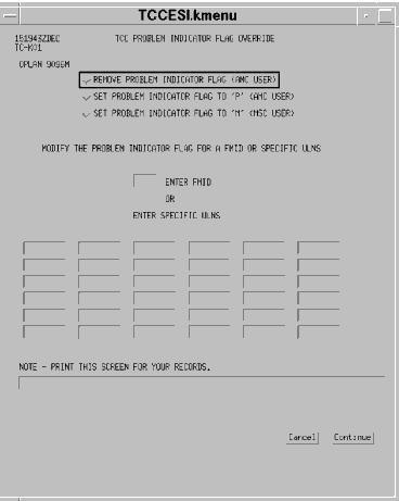
| 1 | Insure 909XT is in the OPLAN field and <POINT AND CLICK (left)> on the TCC PROBLEM INDICATOR FLAG OVERRIDE button. | The TCC Problem Indicator Flag Override button depresses. |
| 2 | <POINT AND CLICK (left)> on the Continue button. | The TCC PROBLEM INDICATOR FLAG OVERRIDE window (Fig. 5-31) displays. |
 |
The MSC validator should identify a force module or any ULNs with an SSF field entry when the SPOE and/or the SPOD needs to be modified to reflect the appropriate shipping itinerary. By Selecting the Set Problem Indicator Flag to 'M' toggle and entering the force module or the ULNs on the window and using the Continue button, the PIF of those records will be changed to an "M". This option is used by the MSC validator to override the locked OPLAN rules (regarding the SPOE and the SPOD) for the modification of validated requirements.
No other changes are authorized or available. If hardcopy of this force module or these ULNs is desired, write them down.
Note: If you were the AMC validator, then you would do the following.
| TCC PROBLEM INDICATOR FLAG OVERRIDE | ||
|---|---|---|
| 3 | <POINT AND CLICK (left)> on the Set Problem Indicator flag to "P" button. | The Set Problem Indicator Flag to "P" button depresses. |
| 4 | Type "9b2aq" and "9b0c2" in the ULN fields. | 9B2AQ and 9B0C2 post in the ULN fields. |
| 5 | <POINT AND CLICK (left)> on the Continue button. | The TCC PROBLEM INDICTOR FLAG OVERRIDE window with an advisory message (Fig. 5-31) redisplays. |
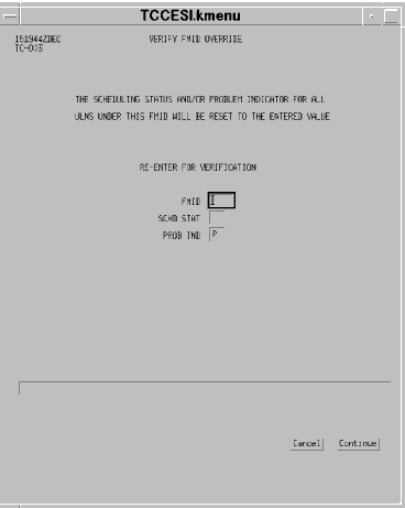
If the Force module option is used, then a confirmation window (Fig. 5-32) requires the validator to reenter the force module for verification.
 |
Now that those records have been clearly flagged to ensure that everyone knows which records are under discussion, USTRANSCOM will continue to coordinate with the supported command and pass on AMC's recommendation for deploying these four people.
Requirement. You will now play the role of the USTRANSCOM Site Validator again. Teleconference coordination with the supported command produces an agreement to move these four individuals by the most expeditious and cost effective method of transportation which is the use of a commercial airline ticket. The appropriate mode and source code to the POD for these two records is "P" "C." The supported command agrees to modify these two records to reflect that movement.
| USTC STATUS/PROBLEM FLAGS OVERRIDE | ||
|---|---|---|
| Step | Activity | Anticipated Result |
| 1 | Insure 909XT is in the OPLAN field and <POINT AND CLICK (left)> on the USTC Status/Problem Indicator Flags Override toggle. | The USTC Status/Problem Flags Override toggle depresses. |
| 2 | <POINT AND CLICK (left)> on the Continue button. | The USTC STATUS/PROBLEM FLAGS OVERRIDE window (Fig. 5-33) displays. |
 |
En Mass.
When the USTC validator selects the FMID toggle, then the FMID field requires an entry. The SCHD STAT and PROB IND fields function in the same way as for the OPLAN choice.
When using the OPLAN or force module options, the SSF for records that have been manifested will not change. In order to change those records, demanifesting (changing the SSF codes of "M" or "B") must occur first. PIF rules are the same as overriding by an individual ULN.
| USTC STATUS/PROBLEM FLAGS OVERRIDE | ||
|---|---|---|
| 3 | <POINT AND CLICK (left)> on the Specific ULNs toggle. | The Specific ULNs toggle depresses. |
| 4 | <POINT AND CLICK (left)> on the first ULN field. | This field becomes active. |
| 5 | Type "9b2aq" in the ULN field, press <TAB>, type "#" in the SCHD STAT field, press <TAB>, and type "#" in the PROB IND field. | 9B2AQ, #, and # post in the appropriate fields. |
| 6 | Press <Tab>, type "9b0c2" in the ULN field, press <TAB>, type "#" in the SCHD STAT field, press <TAB>, and type "#" in the PROB IND field. | 9B0C2, #, and # post in the appropriate fields. |
| 7 | <POINT AND CLICK (left)> on the Continue button. | The USTC STATUS/PROBLEM FLAGS OVERRIDE window with an advisory message (Fig. 5-34) displays. |
 |
| USTC STATUS/PROBLEM FLAGS OVERRIDE | ||
|---|---|---|
| 8 | If the action advisory message was "successful," <POINT AND CLICK (left)> on the Cancel button. | The TCC Interface Subsystem Menu (Fig. 5-17) redisplays. |
Now that you have finished using the flag override features available in the TCCESI software, you should become familiar with how to retrieve records based on some of these flags.
Requirement. GDSS via GTN periodically updates the JOPES database with aircraft itineraries and allocations. CAT personnel at the supported CINC have begun organizing the shift changeover briefing and are desirous of knowing how many of the ULNs that have been validated have aircraft missions scheduled against them. You have been asked to retrieve that information.
| DETERMINE ULN/AIRCRAFT ALLOCATION | ||
|---|---|---|
| Step | Activity | Anticipated Result |
| 1 | <POINT AND DOUBLE CLICK (left)> on the RDA:Edit TPFDD icon. | The RDA:Edit TPFDD window (Fig. 5-13) redisplays. |
| 2 | <POINT AND CLICK (left)> on Select Records. | The Select Records pull-down menu displays. |
| 3 | <POINT AND CLICK (left)> on the User Defined Queries... | The User Defined Queries pop-up displays. |
| 4 | <POINT AND CLICK (left)> on the Create New Query... button. | The RDA:Select Function (Fig 5-14) redisplays. |
| 5 | <POINT AND CLICK (left)> on the Validated Requirements toggle. | The Validation Status pop-up displays. |
| 6 | <POINT AND CLICK (left)> on the A - Allocated to Carrier(s) pick in the pick-list. | The A - Allocated to Carrier(s) line is highlighted. |
| 7 | <POINT AND CLICK (left)> on the Add button. | A - Allocated to Carrier(s) posts in the Selected box. |
| 8 | <POINT AND CLICK (left)> on the Accept button. | Validated Requirements = A posts to the Current Selection Criteria box. |
| 9 | <POINT AND CLICK (left)> on the Apply button. | The Answer Dialogue pop-up displays. |
| 10 | <POINT AND CLICK (left)> on the Replace button. | The records that meet the current retrieval criteria replace the records meeting the previous retrieval criteria in the RDA:Edit TPFDD window. |
| 11 | <POINT AND CLICK (left)> on the Close button. | The RDA:Select Function window closes leaving the RDA:Edit TPFDD window (Fig. 5-13). |
Note. When the SSFs of "V" for validated and "T" for pulled were added to the database, they were basically done in blocks of records, either as force modules or all records meeting certain criteria for the mode and source to the POD. When AMC schedules aircraft to satisfy movement requirements, the "T"s in the database will periodically change to "A"s as the missions are created and GDSS via GTN automatically updates JOPES.
Entered Automatically into JOPES via GTN. Manifesting information can also be entered into JOPES via the GTN interface with JOPES. GTN is the system that collects manifesting and movement data from numerous other sources.
SSF Changes. After manifesting information is entered into JOPES (either manually or automatically), the SSF field would display the appropriate code.
If the ULN had not gone through the entire process, i.e., it had not been validated (V) and consequently not pulled, then the SSF code would be an "M," for manifested but not validated.
You have now completed a tour of all but one of the TCCESI application options. Next you will take a look at the Reports and Utilities option.
| REPORTS AND UTILITIES | ||
|---|---|---|
| Step | Activity | Anticipated Result |
| 1 | Insure 909XT is in the OPLAN field and <POINT AND CLICK (left)> on the Reports and Utilities toggle. | The Reports and Utilities toggle depresses. |
| 2 | <POINT AND CLICK (left)> on the Continue button. | The REPORTS AND UTILITIES window (Fig. 5-35) displays. |
 |
Delete/List Carriers. This option provides a follow-on window that allows the user to delete or list various carriers on the database or on a specified OPLAN.
Delete TCC Interface Files for an OPLAN. When the Supported CINC Validation Option and/or the USTC Requirements Pull Options were executed, they automatically created several files that were used to generate the Plan Compare and Requirements Pull reports. This utility has been added to the TCCESI application to facilitate the management of these files by accomplishing their deletion after the deployment phase of the OPLAN is complete.
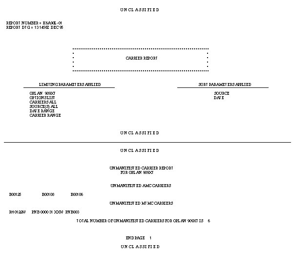
Requirement. Occasionally, GTN will successfully pass a mission schedule and itinerary to JOPES but the allocation or manifesting information associated with that ULN and that mission will be scrambled. You are on duty at the USTRANSCOM CAT and have been asked to check to see if there are any missions of any type in the database that have no allocated ULNs, i.e., carrying no requirements.
| LISTING UNALLOCATED/UNMANIFESTED CARRIERS | ||
|---|---|---|
| Step | Activity | Anticipated Result |
| 1 | Insure 909XT is in the OPLAN field and <POINT AND CLICK (left)> on the Delete/List Carriers toggle. | The Delete/List Carriers toggle depresses. |
| 2 | <POINT AND CLICK (left)> on the Continue button. | The DELETE/LIST CARRIERS window (Fig. 5-36) displays. |
 |
Carriers. At least one of these options must be selected. The user may also select any combination of manifested/unmanifested/allocated/unallocated.
Source(s). At least one of these options must be selected. Again, the user may select any combination of carriers.
Carrier Date Range. Entries in this section are optional. If desired, the user can enter a date range in Relative (C-Day) format by using the first two fields, or in Zulu (Calendar day) format by using the last two fields.
Carrier Name Range. Entries in this section are also optional. If desired, the user can enter a range of carrier names. The only restriction is that the carrier names must exist.
| LISTING UNALLOCATED/UNMANIFESTED CARRIERS | ||
|---|---|---|
| 3 | <POINT AND CLICK (left)> on the List Carriers on OPLAN toggle. | The List Carriers on OPLAN toggle depresses. |
| 4 | <POINT AND CLICK (left)> on the All Carriers toggle. | The All Carriers toggle depresses. |
| 5 | <POINT AND CLICK (left)> on the All Sources toggle. | The All Sources toggle depresses. |
| 6 | <POINT AND CLICK (left)> on the Continue button. | The REPORTS AND UTILITIES window with an advisory message in the message line (Fig. 5-37) displays. |
 |
 |
| DELETE TCC INTERFACE FILES FOR AN OPLAN | ||
|---|---|---|
| Step | Activity | Anticipated Result |
| 1 | Insure 909XT is in the OPLAN field and <POINT AND CLICK (left)> on the Delete TCC Interface Files for an OPLAN toggle. | The Delete TCC Interface Files for an OPLAN toggle depresses. |
| 2 | <POINT AND CLICK (left)> on the Continue button. | The REPORTS AND UTILITIES window with an advisory message in the message line (Fig. 5-39) displays. |
 |
These files will be resident in two locations. They will be on the servers servicing USTRANSCOM and the supported CINC involved with this OPLAN.
Now that you have a good working knowledge of the capabilities of the TCCESI application and what it does, it is time for you to demonstrate your capabilities.
Requirement. The United Nations has reconvened and decided to impose economic sanctions against the aggressor. The United States has agreed to delay any type of military action. No US forces have arrived in theater (it is still early on 1 Jan 96). All airborne aircraft are returning to their POEs. You are the individual directed to return your OPLAN back to it's "on-the-shelf" status. Your actions fall into three broad categories.
1. Remove all carrier information from your OPLAN.
2. Remove all SSFs and PIFs from your OPLAN.
3. Remove all files created by the use of the TCCESI application for your OPLAN from your site.
In addition:
4. Save your OPLAN to your user storage area.
| PRACTICAL EXERCISE - TCCESI APPLICATION | |||
|---|---|---|---|
| Step | Problem | Action/Solution | Accomplished By |
| 5.4 | Delete carrier information | ||
| 5.5 | Reset Schedule Status and Problem Indictor Flags | ||
| 5.6 | Delete TCCESI application created files | ||
| 5.7 | Save OPLAN/TPFDD data to user storage area. | ||
OBJECTIVE. Without references, delete an OPLAN from the database.
| MODIFY/DELETE OPLAN | ||
|---|---|---|
| Step | Activity | Anticipated Result |
| 1 | From the system services Menu, <POINT AND CLICK (left)> on the GCCS System Services Menu bar. | The GCCS System Services Pull-down Menu displays. |
| 2 | <POINT AND CLICK (left)> on Plan Management. | The Plan Management menu displays. |
| 3 | <POINT AND CLICK (left)> on Plan Maintenance. | The INITIAL PLAN MAINTENANCE window (Fig. 5-8) redisplays. |
| 4 | Type "909xt" in the Plan ID field. | 909XT posts in the Plan ID field. |
| 5 | <POINT AND CLICK (left)> on the Delete toggle. | The Delete toggle depresses. |
| 6 | <POINT AND CLICK (left)> on the Transmit button. | The Delete OPLAN? pop-up displays. |
| 7 | <POINT AND CLICK (left)> on Yes. | The Delete OPLAN Network Wide? pop-up displays. |
| 8 | <POINT AND CLICK (left)> on Yes. | The PLAN MAINTENANCE window with an advisory message (Fig. 5-8) redisplays. |
Networked OPLANs. A networked plan can be deleted from a specific site by its creator, the Site FM, or the Network FM, if the FMs have access. It can be deleted network wide by the plan creator or the Network FM, if the FM has access.
This completes your lesson on actions that could be required to support a crisis situation. You can now close all the open applications and return to the Launch Window.
Summary. During this lesson you took a TPFDD from a floppy disk (or resident in a file) and loaded it into the JOPES database. Then you concentrated on the Validation, Pull, Allocation, and Manifesting processes. You became familiar with the effect of an OPLAN's Locked/Unlocked status and how the validation through manifesting sequence affects an OPLAN. We talked about Scheduling Status Flags (SSFs) and Problem Indicator Flags (PIFs). Then we demonstrated the TCCESI application as it supports the validation through manifesting processes. You even deleted an OPLAN from the database after saving it to a file.