
Uranium Production
History and Usage of Uranium
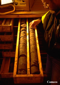
Uranium, not as rare as once thought, is now considered to be more plentiful than mercury, antimony, silver, or cadmium, and is about as abundant as molybdenum or arsenic. It occurs in numerous minerals such as pitchblende, uraninite, carnotite, autunite, uranophane, and tobernite. It is also found in phosphate rock, lignite, monazite sands, and can be recovered commercially from these sources.
 Uranium can be prepared by reducing uranium halides with alkali or alkaline earth metals or by reducing uranium oxides by calcium, aluminum, or carbon at high temperatures. The metal can also be produced by electrolysis of KUF5 or UF4, dissolved in a molten mixture of CaCl2 and NaCl. High-purity uranium can be prepared by the thermal decomposition of uranium halides on a hot filament.
Yellow-colored glass, containing more than 1percent uranium oxide and dating back to 79 A.D., has been found near Naples, Italy. Klaproth recognized an unknown element in pitchblende and attempted to isolate the metal in 1789. The metal apparently was first isolated in 1841 by Peligot, who reduced the anhydrous chloride with potassium.
Uranium is a heavy, silvery-white metal which is pyrophoric when finely divided. It is a little softer than steel, and is attacked by cold water in a finely divided state. It is malleable, ductile, and slightly paramagnetic. In air, the metal becomes coated with a layer of oxide. Acids dissolve the metal, but it is unaffected by alkalis. Finely divided uranium metal, being pyrophoric, presents a fire hazard. Working with uranium requires the knowledge of the maximum allowable concentrations that may be inhaled or ingested. Recently, the natural presence of uranium in many soils has become of concern to homeowners because of the generation of radon and its daughters.
Uranium is used in inertial guidance devices, in gyro compasses, as counterweights for aircraft control surfaces, as ballast for missile reentry vehicles, and as a shielding material. Uranium metal is used for X-ray targets for production of high-energy X-rays; the nitrate has been used as a photographic toner, and the acetate is used in analytical chemistry.
Uranium-235, while occuring in natural uranium to the extent of only 0.71percent, is so fissionable with slow neutrons that a self-sustaining fission chain reaction can be made in a reactor constructed from natural uranium and a suitable moderator, such as heavy water or graphite, alone.
Uranium gun-assembled weapons are the easiest of all nuclear devices to design and build. It is generally conceded to be impossible to prevent any nation having the requisite amount of highly enriched uranium (HEU) from building one or more gun-assembled weapons. Therefore, the acquisition of significant quantities of U-235 or a facility in which to separate the fissile material is an indicator that the acquiring state could be in the process of gaining a rudimentary nuclear capability.
Because HEU is used in certain research reactors, another interpretation is possible. Because of the weapons potential, the United States and France have sought to replace HEU-fueled reactors with ones using a lower grade (more than 20 percent U-235, for example) of uranium which cannot be so readily converted to weapons use. The uranium gun-bomb route was successfully taken by South Africa. Any nation having uranium ore in sufficient quantity, a sufficiently well-developed technological and industrial infrastructure, sufficient electric power, and the desire to acquire nuclear weapons might well choose the uranium gun technology.
Enriching Uranium
A state selecting uranium for its weapons must obtain a supply of uranium ore and construct an enrichment plant because the U-235 content in natural uranium is over two orders of magnitude lower than that found in weapons grade uranium ( more than 90 percent U-235). Ordinary natural uranium contains only 0.72 percent U-235, the highly fissionable isotope, the rest of the material being largely the much less fissionable isotope U-238 (which cannot sustain a chain reaction). The fissile material must be separated from the rest of the uranium by a process known as enrichment. Uranium enriched to 20 percent or more U-235 is called HEU. Uranium enriched above the natural U-235 abundance but to less than 20 percent is called low-enriched (LEU). Several enrichment techniques have been used.
The earliest successful methods were electromagnetic isotope separation (EMIS), in which large magnets are used to separate ions of the two isotopes, and gaseous diffusion, in which the gas uranium hexafluoride (UF6) is passed through a porous barrier material; the lighter molecules containing U-235 penetrate the barrier slightly more rapidly, and with enough stages significant separation can be accomplished. The first large-scale uranium enrichment facility, the Y-12 plant at Oak Ridge, Tennessee, used EMIS in devices called "calutrons." The process was abandoned in the United States because of its high consumption of electricity, but was adopted by the Iraqis because of its relative simplicity and their ability to procure the magnet material without encountering technology transfer obstacles. Both gaseous diffusion and EMIS require enormous amounts of electricity.
More efficient methods have been developed. The third method in widespread use is the gas centrifuge [Urenco (Netherlands, Germany, UK), Russia, Japan] in which UF6 gas is whirled inside complex rotor assemblies and centrifugal force pushes molecules containing the heavier isotope to the outside. Again, many stages are needed to produce the highly enriched uranium needed for a weapon, but centrifuge enrichment requires much less electricity than either of the older technologies.
Atomic and molecular laser isotope separation (LIS) techniques use lasers to selectively excite atoms or molecules containing one isotope of uranium so that they can be preferentially extracted. Although LIS appears promising, the technology has proven to be extremely difficult to master and may be beyond the reach of even technically advanced states.
The South African nuclear program used an aerodynamic separation technique in an indigenously designed and built device called a vortex tube. In the vortex a mixture of UF6 gas and hydrogen is injected tangentially into a tube, which tapers to a small exit aperture at one or both ends; centrifugal force provides the separation. The Becker Nozzle Process, also an aerodynamic separation technique, was developed in Germany. The Becker process is not in common use; the vortex tube was used in South Africa for producing reactor fuel with a U-235 content of around 3 to 5 percent in addition to making 80 to 93 percent U-235 for the weapons program. Aerodynamic enrichment processes require large amounts of electricity and are not generally considered economically competitive; even the South African enrichment plant has apparently been closed.
Separative Work Unit (SWU) is a complex unit which is a function of the amount of uranium processed and the degree to which it is enriched, ie the extent of increase in the concentration of the U-235 isotope relative to the remainder. The unit is strictly: Kilogram Separative Work Unit, and it measures the quantity of separative work (indicative of energy used in enrichment) when feed and product quantities are expressed in kilograms. The effort expended in separating a mass F of feed of assay xf into a mass P of product assay xp and waste of mass W and assay xw is expressed in terms of the number of separative work units needed, given by the expression SWU = WV(xw) + PV(xp) - FV(xf), where V(x) is the "value function," defined as V(x) = (1 - 2x) ln((1 - x)/x). For instance, to produce one kilogram of uranium enriched to 3.5 percent U-235 requires 4.3 SWU if the plant is operated at a tails assay 0.30 percent, or 4.8 SWU if the tails assay is 0.25 percent (thereby requiring only 7.0 kg instead of 7.8 kg of natural U feed). About 100-120,000 SWU is required to enrich the annual fuel loading for a typical 1000 MWe light water reactor. Enrichment costs are related to electrical energy used. The gaseous diffusion process consumes some 2400 kWh per SWU, while gas centrifuge plants require only about 60 kWh/SWU.
Feedstock for Enrichment Plants
 Gaseous uranium hexafluoride (UF6) is used as the feed in the gas centrifuge and gaseous diffusion processes, and uranium tetrachloride (UCl4) is used as feed in the electromagnetic isotope separation (EMIS) process. Nearly all uranium enrichment plants utilize UF 6 as their feed.
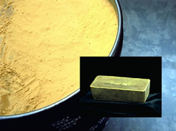
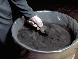
Uranium ore concentrates, also known as yellowcake, typically contain 60–80 percent uranium and up to 20 percent extraneous impurities. There are two commercial processes used to produce purified UF6 from yellowcake. The primary difference between the two processes -- solvent extraction/fluorination (“wet process”) and fluorination / fractionation (“dry process”) -- is whether the uranium is purified by sol-vent extraction before conversion to UF6 or by fractional distillation of the UF6 after conversion.
In the wet process, yellowcake is dissolved in nitric acid (HNO3), and the in-soluble residue is removed by filtration or centrifugation. Uranium is separated from the acid solution with liquid-liquid extraction, the uranyl nitrate product is decomposed to uranium trioxide (UO3) via thermal denitration, and the trioxide is reduced to uranium dioxide (UO2) with hydrogen or cracked ammonia (NH3). In most cases, the standard Purex process, using tri-n-butyl phosphate (TBP) in a hydrocarbon diluent, separates uranium from its impurities in the extraction step. In the dry process, the conversion and purification steps occur throughout the process. If the yellowcake was produced by the alkali-leach process (yields Na2U2O7), the sodium must be removed from the material by partial digestion in sulfuric acid followed by ammonia precipitation of ammonium diuranate [(NH4)2U2O7]. The ammonium-containing uranium salt is decomposed to UO3 by heating, and this oxide is reduced to UO2 with hydrogen or cracked NH3 .
 The remaining steps used to produce UF6 for both processes are similar in that the UO2 is converted to UF4 by hydrofluorination (using hydrogen fluoride gas—HF). The UF4 (impure in the dry process) is converted to UF6 using electrolytically generated fluorine gas (F2). In the dry process, the UF6 is purified in a two-stage distillation step. Direct fluorination of UO3 to UF6 has been used, but this procedure is more amenable to relatively small capacity plants.
The EMIS uranium-enrichment process uses UCl4 for its feed material. Uranium tetrachloride is produced by the reaction of carbon tetrachloride (CCl4 ) with pure UO2 at 700 °F.
Many countries around the world have extracted uranium from its ores or from yellowcake. The processes for preparing the feedstocks are basic industrial chemistry. The enabling technologies are those which use HF, NH3 , F2 , CCl4 , and precursor uranium compounds to prepare UF6 and UCl4.
Enrichment Techniques
Uranium-235 is of particular interest because it is the only fissile material that occurs in nature in significant quantity, and it can be used to construct a nuclear explosive device if a sufficient quantity can be acquired. In a typical sample of natural uranium, only 0.72 percent of the atoms are U-235 atoms, and it can be assumed that all of the remaining atoms are U-238 atoms. Natural uranium typically has a composition of 0.0055 percent U-234, 0.7205 percent U-235, and 99.274 percent U-238. For most purposes, the tiny fraction of U-234 can be neglected. Higher concentrations of U-235 are required for many applications, and the use of uranium isotope separation processes to increase the assay of U-235 above its natural value of 0.72 percent is called uranium enrichment.
While low-enriched uranium (LEU) could technically mean uranium with an assay anywhere between slightly greater than natural (0.72 percent) and 20 percent U-235, it most commonly is used to denote uranium with an assay suitable for use in a light-water nuclear reactor (i.e., an assay of less than 5 percent). Similarly, the term “highly enriched” uranium (HEU) could be used to describe uranium with an assay greater than 20 percent, but it is commonly used to refer to uranium enriched to 90 percent U-235 or higher (i.e., weapons-grade uranium). The term “oralloy” was used during World War II as a con-traction of “Oak Ridge alloy,” and it denoted uranium enriched to 93.5 percent U-235.
Manhattan Project scientists and engineers explored several uranium-enrichment technologies, and production plants employing three uranium-enrichment processes —- electromagnetic isotope separation (EMIS), liquid thermal diffusion, and gaseous diffusion -- were constructed at Oak Ridge, Tennessee, during the period from 1943 to 1945. Centrifugation was tried, but the technology needed to spin a rotor at an appropriate speed was not then practical on an industrial scale. The aerodynamic separation processes developed in Germany and South Africa did not exist during World War II; neither, of course did laser isotope separation or plasma separation. The World War II Japanese nuclear program made some attempts to find a purely chemical process.
Electromagnetic Isotope Separation
The EMIS process is based on the same physical principle as that of a simple mass spectrometer -— that a charged particle will follow a circular trajectory when passing through a uniform magnetic field. Two ions with the same kinetic energy and electrical charge, but different masses (i.e. U-235+ and U238+), will have different trajectories, with the heavier U-238+ ion having the larger diameter. The different diameters of the trajectories of the two uranium ions allow for the separation and collection of the material in receivers or “collector pockets.” EMIS is a batch process that can produce weapons-grade material from natural uranium in only two stages. However, hundreds to thousands of units would be required to produce large quantities of HEU because of the process’s relatively low product collection rate and the long cycle time required to recover material between runs.
In the uranium EMIS process, uranium ions are generated within an evacuated enclosure (called a “tank”) that is located in a strong magnetic field. For the EMIS ion source, solid uranium tetrachloride (UCl4 ) is electrically heated to produce UCl4 vapor. The UCl4 molecules are bombarded with electrons, producing U+ ions. The ions are accelerated by an electrical potential to high speed and follow a circular trajectory in the plane perpendicular to the magnetic field. In the U.S. EMIS separators, the ion beam traverses a 180-deg arc before the ions pass through slit apertures at the collector. A major problem with the EMIS process is that less than half of the UCl4 feed is typically converted to the desired U + ions, and less than half of the desired U + ions are actually collected. Recovery of unused material deposited on the interior surfaces of the tanks is a laborious, time-consuming process that reduces the effective output of an EMIS facility and requires a large material recycle operation.
In the U.S. EMIS program, production of weapons-grade uranium took place in two enrichment stages, referred to as the a and b stages. The first (a) stage used natural or slightly enriched uranium as feed and enriched it to 12 to 20 percent U-235. The second (b) stage used the product of the (a) stage as feed and further enriched it to weapons-grade uranium. To allow more efficient use of magnets and floor space, the individual stages were arranged in continuous oval or rectangular arrays (called “race-tracks” or, simply, “tracks”) with separator tanks alternated with electromagnetic units. The U.S. EMIS separators are referred to as “calutrons” because the development work was carried out at the University of California (Berkeley) during the early 1940’s using cyclotrons.
Although most applications of the EMIS process have been applied to the commercial production of both stable and radioactive isotopes, all five recognized weapons states have tested or used the EMIS process for uranium enrichment. Even with the problems associated with using the process, an EMIS facility could be attractive for a country desiring a limited weapons-grade uranium enrichment program. The process might be especially appealing as a method for further enriching partially enriched material. It has been well documented that EMIS was the principal process pursued by the Iraqi uranium enrichment program. This occurred at a time when EMIS had been discarded and largely forgotten as a method for uranium enrichment because it is both energy intensive and labor intensive, and it is not economically competitive with other enrichment technologies.
Thermal Diffusion
Thermal diffusion utilizes the transfer of heat across a thin liquid or gas to accomplish isotope separation. By cooling a vertical film on one side and heating it on the other side, the resultant convection currents will produce an upward flow along the hot surface and a downward flow along the cold surface. Under these conditions, the lighter U-235 gas molecules will diffuse toward the hot surface, and the heavier U-238 molecules will diffuse toward the cold surface. These two diffusive motions combined with the convection currents will cause the lighter U-235 molecules to concentrate at the top of the film and the heavier U-238 molecules to concentrate at the bottom of the film.
The thermal-diffusion process is characterized by its simplicity, low capital cost, and high heat consumption. Thermal diffusion in liquid UF 6 was used during World War II to prepare feed material for the EMIS process. A production plant containing 2,100 columns (each approximately 15 meters long) was operated in Oak Ridge for less than 1 year and provided a product assay of less than 1 percent U-235. Each of these columns consisted of three tubes. Cooling water was circulated between the outer and middle tubes, and the inner tube carried steam. The annular space between the inner and middle tubes was filled with liquid UF6.
The thermal-diffusion plant in Oak Ridge was dismantled when the much more energy-efficient (by a factor of 140) gaseous-diffusion plant began operation in the 1940’s. Today, thermal diffusion remains a practical process to separate isotopes of noble gases (e.g. xenon) and other light isotopes (e.g. carbon) for research purposes.
Gaseous Diffusion
The gaseous-diffusion process has been highly developed and employed to pro-duce both HEU and commercial reactor-grade LEU. The United States first employed gaseous diffusion during WWII and expanded its capacity after the war to produce HEU. Since the late 1960’s, the U.S. facilities have been used primarily to produce commercial LEU, with the last remaining HEU capacity being shut down in 1992. China and France currently have operating diffusion plants. Russia’s enrichment facilities have been converted from diffusion to centrifuge technology. Britain’s diffusion facility was shut down and dismantled.
he gaseous-diffusion process depends on the separation effect arising from molecular effusion (i.e., the flow of gas through small holes). On average, lighter gas molecules travel faster than heavier gas molecules and consequently tend to collide more often with the porous barrier material. Thus, lighter molecules are more likely to enter the barrier pores than are heavier molecules. For UF 6 , the difference in velocities between molecules containing U-235 and U-238 is small (0.4 percent), and, consequently, the amount of separation achieved by a single stage of gaseous diffusion is small. Therefore, many cascade stages are required to achieve even LEU assays.
UF6 is a solid at room temperature but becomes a gas when heated above 135 degrees Fahrenheit. The solid UF6 is heated to form a gas, and the gaseous diffusion enrichment process begins. The process separates the lighter U-235 isotopes from the heavier U-238. The gas is forced through a series of porous membranes with microscopic openings. Because the U-235 is lighter, it moves through the barriers more easily. As the gas moves, the two isotopes are separated, increasing the U-235 concentration and decreasing the concentration of U-238.

Diffusion equipment tends to be rather large and consumes significant amounts of energy. The main components of a single gaseous-diffusion stage are (1) a large cylindrical vessel, called a diffuser or converter, that contains the barrier; (2) a compressor used to compress the gas to the pressures needed for flow through the barrier; (3) an electric motor to drive the compressor; (4) a heat exchanger to remove the heat of compression; and (5) piping and valves for stage and interstage connections and process control. The entire system must be essentially leak free, and the compressors require special seals to prevent both out-leakage of UF6 and in-leakage of air. The chemical corrosiveness of UF6 requires use of metals such as nickel or aluminum for surfaces exposed to the gas (e.g. piping and compressors). In addition to the stage equipment, auxiliary facilities for a gaseous-diffusion plant could include a large electrical power distribution system, cooling towers to dissipate the waste process heat, a fluorination facility, a steam plant, a barrier production plant, and a plant to produce dry air and nitrogen.
The production of a sustainable, efficient separating membrane (barrier) is the key to the successful operation of a diffusion plant. To obtain an efficient porous barrier, the holes must be very small (on the order of one-millionth of an inch in diameter) and of uniform size. The porosity of the barrier must be high to obtain high flow rates through the barrier. The barrier must also be able to withstand years of operation while exposed to corrosive UF6 gas. Typical materials for the barrier are nickel and aluminum oxide.
Gaseous diffusion is unlikely to be the preferred technology of a proliferator due to difficulties associated with making and maintaining a suitable barrier, large energy consumption, the requirement for procuring large quantities of specialized stage equipment, large in-process inventory requirements, and long equilibrium times.
Gas Centrifuge
 The use of centrifugal fields for isotope separation was first suggested in 1919; but efforts in this direction were unsuccessful until 1934, when J.W. Beams and co-workers at the University of Virginia applied a vacuum ultracentrifuge to the separation of chlorine isotopes. Although abandoned midway through the Manhattan Project, the gas centrifuge uranium-enrichment process has been highly developed and used to produce both HEU and LEU. It is likely to be the preferred technology of the future due to its relatively low-energy consumption, short equilibrium time, and modular design features.
In the gas centrifuge uranium-enrichment process, gaseous UF6 is fed into a cylindrical rotor that spins at high speed inside an evacuated casing. Because the rotor spins so rapidly, centrifugal force results in the gas occupying only a thin layer next to the rotor wall, with the gas moving at approximately the speed of the wall. Centrifugal force also causes the heavier 238-UF6 molecules to tend to move closer to the wall than the lighter 235-UF6 molecules, thus partially separating the uranium isotopes. This separation is increased by a relatively slow axial countercurrent flow of gas within the centrifuge that concentrates enriched gas at one end and depleted gas at the other. This flow can be driven mechanically by scoops and baffles or thermally by heating one of the end caps.
The main subsystems of the centrifuge are (1) rotor and end caps; (2) top and bottom bearing/suspension system; (3) electric motor and power supply (frequency changer); (4) center post, scoops and baffles; (5) vacuum system; and (6) casing. Because of the corrosive nature of UF6, all components that come in direct contact with UF6 must be must be fabricated from, or lined with, corrosion-resistant materials. The separative capacity of a single centrifuge increases with the length of the rotor and the rotor wall speed. Consequently, centrifuges containing long, high-speed rotors are the goal of centrifuge development programs (subject to mechanical constraints).
The primary limitation on rotor wall speed is the strength-to-weight ratio of the rotor material. Suitable rotor materials include alloys of aluminum or titanium, maraging steel, or composites reinforced by certain glass, aramid, or carbon fibers. At present, maraging steel is the most popular rotor material for proliferants. With maraging steel, the maximum rotor wall speed is approximately 500 m/s. Fiber-rein-forced composite rotors may achieve even higher speeds; however, the needed com-posite technology is not within the grasp of many potential proliferants. Another limitation on rotor speed is the lifetime of the bearings at either end of the rotor. Rotor length is limited by the vibrations a rotor experiences as it spins. The rotors can undergo vibrations similar to those of a guitar string, with characteristic frequencies of vibration. Balancing of rotors to minimize their vibrations is especially critical to avoid early failure of the bearing and suspension systems. Because perfect balancing is not possible, the suspension system must be capable of damping some amount of vibration.
One of the key components of a gas centrifuge enrichment plant is the power supply (frequency converter) for the gas centrifuge machines. The power supply must accept alternating current (ac) input at the 50- or 60-Hz line frequency available from the electric power grid and provide an ac output at a much higher frequency (typically 600 Hz or more). The high-frequency output from the frequency changer is fed to the high-speed gas centrifuge drive motors (the speed of an ac motor is proportional to the frequency of the supplied current). The centrifuge power supplies must operate at high efficiency, provide low harmonic distortion, and provide precise control of the output frequency.
The casing is needed both to maintain a vacuum and to contain the rapidly spinning components in the event of a failure. If the shrapnel from a single centrifuge failure is not contained, a “domino effect” may result and destroy adjacent centrifuges. A single casing may enclose one or several rotors.
Although the separation factors obtainable from a centrifuge are large compared to gaseous diffusion, several cascade stages are still required to produce even LEU material. Furthermore, the throughput of a single centrifuge is usually small, which leads to rather small separative capacities for typical proliferator centrifuges. To be able to produce only one weapon per year, several thousand centrifuges would be required.
The electrical consumption of a gas centrifuge facility is much less than that of a gaseous diffusion plant. Consequently, a centrifuge plant will not have the easily identified electrical and cooling systems typically required by a gaseous diffusion plant.
Aerodynamic Processes
Aerodynamic uranium enrichment processes include the separation nozzle process and the vortex tube separation process. These aerodynamic separation processes depend upon diffusion driven by pressure gradients, as does the gas centrifuge. In effect, aerodynamic processes can be considered as non-rotating centrifuges. Enhancement of the centrifugal forces is achieved by dilution of UF6 with a carrier gas (i.e., hydrogen or helium). This achieves a much higher flow velocity for the gas than could be obtained using pure UF6 .
The separation nozzle process was developed by E.W. Becker and associates at the Karlsruhe Nuclear Research Center in Germany. In this process, a mixture of gaseous UF6 and H2 (or helium) is compressed and then directed along a curved wall at high velocity. The heavier U-238-bearing molecules move preferentially out to the wall relative to those containing U-235. At the end of the deflection, the gas jet is split by a knife edge into a light fraction and a heavy fraction, which are withdrawn separately.
Economic considerations drive process designers to select separation nozzles with physical dimensions as small as manufacturing technology will allow. The curved wall of the nozzle may have a radius of curvature as small as 10 mm (0.0004 in). Production of these tiny nozzles by such processes as stacking photo-etched metal foils is technically demanding. A typical stage consists of a vertical cylindrical vessel containing the separation elements, a cross piece for gas distribution, a gas cooler to remove the heat of compression, and a centrifugal compressor driven by a electric motor.
The Uranium Enrichment Corporation of South Africa, Ltd. (UCOR) developed and deployed its own aerodynamic process characterized as an “advanced vortex tube” or “stationary-walled centrifuge” at the so called “Y” plant at Valindaba to produce hundreds of kilograms of HEU. In this process, a mixture of UF6 and H2 is compressed and enters a vortex tube tangentially at one end through nozzles or holes at velocities close to the speed of sound. This tangential injection of gas results in a spiral or vortex motion within the tube, and two gas streams are withdrawn at opposite ends of the vortex tube. The spiral swirling flow decays downstream of the feed inlet due to friction at the tube wall. Consequently, the inside diameter of the tube is typically tapered to reduce the decay in the swirling flow velocity. This process is characterized by a separating element with very small stage cut (ratio of product flow to feed flow) of about 1/20 and high process-operating pressures.
Due to the very small cut of the vortex tube stages and the extremely difficult piping requirements that would be necessary based on traditional methods of piping stages together, the South Africans developed a cascade design technique, called Helikon. In essence, the Helikon technique permits 20 separation stages to be combined into one large module, and all 20 stages share a common pair of axial-flow compressors. A basic requirement for the success of this method is that the axial-flow compressors successfully transmit parallel streams of different isotopic compositions without significant mixing. A typical Helikon module consists of a large cylindrical steel vessel that houses a separating element assembly, two axial-flow compressors (one mounted on each end), and two water-cooled heat exchangers.
For both of these aerodynamic processes, the high proportion of carrier gas required in relation to UF6 process gas results in high specific-energy consumption and substantial requirements for removal of waste heat.
Laser Isotope Separation
In the early 1970’s, significant work began on the development of laser isotope separation technologies for uranium enrichment. Present systems for enrichment processes using lasers fall into two categories: those in which the process medium is atomic uranium vapor and those in which the process medium is the vapor of a uranium compound. Common nomenclature for such processes include “first category— atomic vapor laser isotope separation (AVLIS or SILVA)” and “second category— molecular laser isotope separation (MLIS or MOLIS).”
The systems, equipment, and components for laser-enrichment plants embrace (a) devices to feed uranium-metal vapor (for selective photoionization) or devices to feed the vapor of a uranium compound (for photo-dissociation or chemical activation); (b) devices to collect enriched and depleted uranium metal as product and tails in the first category and devices to collect dissociated or reacted compounds as product and unaffected material as tails in the second category; (c) process laser systems to selectively excite the U 235 species; and (d) feed preparation and product conversion equipment. The complexity of the spectroscopy of uranium atoms and compounds may require incorporation of any number of available laser technologies.
AVLIS
The atomic vapor laser isotope separation (AVLIS) process is based on the fact that U-235 atoms and U-238 atoms absorb light of different frequencies (or colors). Al-though the absorption frequencies of these two isotopes differ only by a very small amount (about one part in a million), the dye lasers used in AVLIS can be tuned so that only the U-235 atoms absorb the laser light. As the U-235 atom absorbs the laser light, its electrons are excited to a higher energy state. With the absorption of sufficient energy, a U-235 atom will eject an electron and become a positively charged ion. The U-235 ions may then be deflected by an electrostatic field to a product collector. The 238 U atoms remain neutral and pass through the product collector section and are deposited on a tails collector.
The AVLIS process consists of a laser system and a separation system. The separator system contains a vaporizer and a collector. In the vaporizer, metallic uranium is melted and vaporized to form an atomic vapor stream. The vapor stream flows through the collector, where it is illuminated by the precisely tuned laser light. The AVLIS laser system is a pumped laser system comprised of one laser used to optically pump a separate dye laser, which produces the light used in the separation process. Dye master oscillator lasers provide precise laser beam frequency, timing, and quality control. The laser light emerging from the dye master oscillator laser is increased in power by passage through a dye laser amplifier. A total of three colors are used to ionize the U-235 atoms.
Many countries are pursuing some level of AVLIS research and/or development, and major programs exist in the United States, France, Japan, and probably Russia. Principal advantages of the AVLIS process include a high separation factor, low energy consumption (approximately the same as the centrifuge process), and a small volume of generated waste. However, no country has yet deployed an AVLIS process, although several have demonstrated the capability to enrich uranium with the process.
While conceptually simple, the actual implementation of the process is likely to be difficult and expensive, especially for countries with limited technical resources. The AVLIS process requires much sophisticated hardware constructed of specialized materials that must be capable of reliable operation for extended periods of time in a harsh environment.
MLIS
The idea for the molecular laser isotope separation (MLIS) process was conceived by a group of scientists at the Los Alamos National Laboratory in 1971. There are two basic steps involved in the MLIS process. In the first step, UF 6 is irradiated by an infrared laser system operating near the 16 mm wavelength, which selectively excites the 235-UF6, leaving the 238-UF6 relatively unexcited. In the second step, photons from a second laser system (infrared or ultraviolet) preferentially dissociate the excited 235-UF6 to form 235-UF5 and free fluorine atoms. The 235-UF5 formed from the dissociation precipitates from the gas as a powder that can be filtered from the gas stream.
MLIS is a stagewise process, and each stage requires conversion of the enriched UF5 product back to UF6 for further enrichment. CO2 lasers are suitable for exciting the 235-UF6 during the first step. A XeCl excimer laser producing ultraviolet light may be suitable for the dissociation of 235-UF6 during the second step. However, there is currently no known MLIS optical system which has been successfully designed to handle both infrared and ultraviolet. Consequently, most MLIS concepts use an all infrared optical system.
In terms of the gas flow for the MLIS process, gaseous UF6 mixed with a carrier gas and a scavenger gas is expanded through a supersonic nozzle that cools the gas to low temperatures. Hydrogen or a noble gas are suitable as carriers. A scavenger gas (such as methane) is used to capture the fluorine atoms that are released as a result of the dissociation of 235-UF6 molecules.
There are many complexities associated with the process, and the United States, UK, France, and Germany have stated that their MLIS programs have been termi-nated. Japan also has had a small MLIS program. South Africa has recently stated that their MLIS program is ready to be deployed for low-enriched uranium (LEU) production.
Principal advantages of the MLIS process are its low power consumption and its use of UF6 as its process gas.
Chemical and Ion Exchange
Chemical-exchange isotope separation requires segregation of two forms of an element into separate but contacting streams. Since many contacts are required to achieve the desired separation, the contacting process must be fast and achieve as much separation as possible. For heavy elements such as uranium, achieving a suitable separation factor involves contact between two valence (oxidation state) forms such as hexavalent [U6+ as in uranyl chloride (UO2Cl2 )] and the quadrivalent [U4+ as in uranium tetrachloride (UCl4 )]. The 235-U isotope exhibits a slight preference for the higher valence, for example, the hexavalent over the quadrivalent in the Asahi process or the quadrivalent over the trivalent (U3+) in the French solvent-extraction process.
The chemical-exchange process, developed by the French, is commonly referred to as CHEMEX. It uses the exchange reaction that takes place between two valence states (U3+ and U4+) of uranium ions in aqueous solution. Isotopic enrichment results from the tendency of U-238 to concentrate in the U3+ compound while 235-U concentrates in the U4+ compound. It is therefore possible to obtain enriched uranium by removing the U4+ ions with an organic solvent that is immiscible with the aqueous phase (concentrated hydrochloric acid). Several possible extractants are available; however, tributyl phosphate (TBP), the choice of the French, is typically used. TBP is diluted with an aromatic solvent, and this organic phase moves countercurrent to the aqueous phase through a series of pulsed columns.
In the pulse column, the heavier aqueous phase is fed into the top of the column, and the lighter organic phase is fed into the bottom of the column. A rapid reciprocating motion is applied to the contents of the column, providing efficient and intimate contact of the two phases. In an HEU plant, centrifugal contactors might be employed particularly for the higher assay sections, since the stage times and corresponding specific uranium inventory could be reduced significantly. After passing through the column, the enriched and depleted uranium streams must be chemically treated so that they can be recirculated through the column again (refluxed) or sent to another column for additional enrichment. This requires complicated refluxing equipment at both ends of the column.
The ion-exchange process was developed by the Asahi Chemical Company in Japan and uses the chemical isotope effect between two valences (U4+ and U6+ ) of uranium. In this process, the organic phase is replaced by a proprietary ion-exchange resin. The aqueous phase flows through the stationary resin held in a column, and the net effect of all the chemical reactions is a "band" of uranium that moves through the ion-exchange column. The exchange between the unabsorbed uranium flowing through the band and that adsorbed on the resin enhances the isotopic separation. In this continuous separation system, 235-U and 238-U tend to accumulate respectively at the entrance and exit ends of the adsorption band. In this process, it is economical to regenerate many of the chemicals by reaction with oxygen and hydrogen in separate equipment.
The development and manufacture of the appropriate adsorbent beads are based on technology and know-how gained by Asahi in over 25 years of ion-exchange membrane development and manufacture. The adsorbent is a spherical bead of porous anion-exchange resin with a very high separation efficiency and an exchange rate over 1,000 times faster than the rates obtained in most commercially available resins. The two exchange processes discussed here are representative of exchange processes now under study in several countries. At present, no country has built or operated a full-scale uranium enrichment plant based on an exchange process. The primary proliferation concern is that they are based on standard chemical engineering technology (except for the proprietary ion-exchange resins).
Plasma Separation
The plasma separation process (PSP) has been studied as a potentially more efficient uranium-enrichment technique that makes use of the advancing technologies in superconducting magnets and plasma physics. In this process, the principle of ion cyclotron resonance is used to selectively energize the U-235 isotope in a plasma containing U-235 and U-238 ions. A feed plate of solid uranium serves as the source of neutral uranium atoms. These atoms are vaporized by bombarding the plate with energetic ions in a process called sputtering. A microwave antenna located in front of the plate energizes free electrons which collide with neutral uranium atoms in the vapor sputtering off the plate. This in turn displaces electrons from the uranium atoms and produces a plasma of U-235 and U-238 ions.
The plasma is subjected to a uniform magnetic field along the axis of a cylindrical vacuum chamber as the plasma flows from source to collector. The magnetic field is produced by a superconducting magnet located around the outside of the chamber. The high-strength magnetic field produces helical motions of the ions, with the lighter U-235 ions spiraling faster and having a higher ion cyclotron frequency than the heavier U-238 ions. As the ions move toward the collector, they pass through an electric field produced by an excitation coil oscillating at the same frequency as the ion cyclotron frequency of the U-235 ions. This causes the helical orbit of the U-235 ions to increase in radius while having minimal effect on the orbit of the heavier U-238 ions. The plasma flows through a collector of closely spaced, parallel slats, the physical appearance of which roughly resembles a venetian blind. The large-orbit U-235 ions are more likely to deposit on the slats, while the remaining plasma, depleted in U,-235 accumulates on an end plate of the collector. PSP is a batch process that would require several stages to produce HEU from natural feed.
The only countries known to have had serious PSP experimental programs are the United States and France. PSP became a part of DOE's Advanced Isotope Separation research and development program in 1976, but development was dropped in 1982 when AVLIS was chosen as the advanced technology of choice. The French developed their own version of PSP, which they called RCI. Funding for RCI was drastically reduced in 1986, and the program was suspended around 1990, although RCI is still used for stable isotope separation.
Detection of Enrichment Activity
If operated on a large enough scale (perhaps 10 bombs-worth per year), an energy-inefficient enrichment technology such as EMIS or gaseous diffusion might be detectable by its heat emission. At Iraq’s A1-Tarmiya facility, for instance, heat rejection into the air or, as appears to have been planned, into the Tigris river, might well have been observable once operation had begun. However, at lesser production rates or with more efficient technologies (e.g., centrifuges, or EMIS techniques that employed permanent magnets and lower beam-voltages), heat signatures would be less evident. Heat emission is a nonspecific signature, however, that would be most useful for monitoring the startup and shutdown patterns of known facilities; it would have to be combined with other indicators to determine whether a given unknown facility were nuclear-related. If the heat were dischmged into a modest-simd river, a resulting rise in temperature on the order of O. 1“C or more (depending on flow-rate, mixing, etc.) would be detectable in the far-infrared. Alternatively, heat from the cooling towers might also be detectable.
A potential sign of a clandestine enrichment or other nuclear facility could be unexplained special security or military reinforcements around an industrial site. These arrangements might be visible from overhead or from the ground. At close enough range, other signatures would become observable. For example, even a very small centrifuge plant might emit detectable acoustic or radiofrequency noise, and the pulsed lasers used for laser isotope separation emit characteristic electromagnetic signals at kilohertz frequencies that might be detected. Samples of substances taken from either declared or suspect facilities could also indicate their potential for producing weapon materials. For example, UCl4 or other uranium chloride combinations could indicate EMIS or Chemex enrichment technology, and UF6, UF4, HF, or uranium metal could indicate other uranium enrichment techniques. Analysis of environmental samples containing depleted or enriched uranium in water or soil would also provide very important signatures.
Patterns of foreign procurement of essential materials and parts, such as newer high-strength materials or maraging steel (a very high-tensile-strength steel used to manufacture some types of gas centrifuge), or large iron electromagnets, high-voltage power supplies, and large vacuum systems (for EMIS), might also help to indicate a county’s intentions.
An indigenous uranium mining industry might provide early indication of a clandestine uranium or plutonium-based weapon program and is a sure indicator of at least the possibility.
Sources
Adapted from - Nuclear Weapons Technology Militarily Critical Technologies List (MCTL) Part II: Weapons of Mass Destruction Technologies