
3Atmospheric Effects on Electro-optics
Page
3–1. Basic Physics of Radiative Transfer
028. Electro-optical systems
029. Black-body radiation
030. Contrast
031. Contrast transmission
032. Reflected energy systems (other than visual)
033. Wavelength resolution-sensitivity relationships
3–2. Environmental Sensitivities of PGMs
034. Visual systems
035. Infrared systems
3–3. Target Acquisition Systems and Tactics
036. The classic target acquisition cycle (CTAC)
037. Air-to-ground missions
038. Launch envelope
3–4. Principles of Operation of PGMs
039. Three types of PGM systems
040. Employment modes
041. Employment tactics for PGMs
RECISION guided munitions and target acquisition systems represent revolutionary advances in warfare. In Operation Desert Storm, the men and women of the United States Army, Navy, Air Force, and Marines, as well as those of our coalition allies, demonstrated that we can now put ordnance precisely on target any time of day or night. We can do this with maximum effectiveness and without causing extensive collateral damage. Unlike our experience in Vietnam, we can now deny the enemy the cover of night. The successful employment of these weapons is due in no small part to the hard work, skill, and professionalism of forecasters and aerographer’s mates.
Electro-optical (EO) sensors are weather sensitive. To best take advantage of them, it is our responsibility to let our customers know how these systems will function under different meteorological conditions. Using our forecasting skill (and a desktop computer), we can provide our customers with vital information that will help them determine which weapons can be employed effectively and which will be impaired by environmental conditions. Such decisions may prove crucial in combat situations. It is extremely important that you understand your customer’s mission and tactics. You must know not only where the pilot will fly, but what weapons and tactics will be used. Your job will be to forecast what a target scene will look like and from how far away an aircrew will be able to identify its target. You must not only understand how weather affects the aircraft, but how weather affects the weapons it carries.
Our ability to provide weather support to electro-optical systems must be based on an understanding of the effects of the atmosphere on the propagation of electromagnetic energy. Approach the EO forecasting problem as a three-step process. First we are concerned with the actual contrast between targets and backgrounds, both in the visible spectrum and in the infrared. The next step is to forecast the effects of the atmosphere on the image that the aircrew member sees at a distance from the target. The third step, which we leave to the computer, is to account for the performance of the sensor being employed. Once you cover all the significant ideas and details of radiative transfer in the atmosphere, you will be fully prepared to apply this knowledge to tactical decision making.
Aircraft and munitions may be equipped with EO sensors that enable the pilot to find targets and put bombs and missiles on those targets with amazing accuracy from great distances. An EO sensor mounted on the aircraft is called a target acquisition system. If the EO sensor is mounted on the bomb or missile itself, then that munition is called a precision guided munition (PGM). Either type EO system may be designed to display an image of the target to the pilot, aviator, bombardier/navigator (B/N), or weapon system officer (WSO), or it may be designed to detect energy directly reflected by the target. Visual imaging systems depend on the contrast between reflectivities of objects in the target scene. Far infrared (FIR) imaging systems depend on the contrast between emitted thermal energy of the objects in the target scene. Systems designed to detect reflected energy may be either 1.06 micrometers/microns (m m) near infrared (NIR) lasers or millimeter/microwave radars. These systems depend on the target being designated by a laser or illuminated with radar energy.
Electromagnetic radiation (EMR)
The energy that is detected by an EO system is electromagnetic (EM) energy or electromagnetic radiation (EMR). Think of EMR in either of two ways. The first way is as coupled electric and magnetic waves, propagating (transmitting) in the same direction and oriented at right angles to each other.
You are probably already familiar with the visible portion of the EM spectrum. This is what you see when you look at a rainbow. A wave may be characterized by its wavelength (l ) and where this wavelength falls in the electromagnetic spectrum. Wavelengths are measured in micrometers (m m), which is equal to one-millionth of a meter. The wavelengths of visible light range from 0.4m m at the violet end to 0.74m m at the red end. Wavelengths shorter than those of violet light include the ultraviolet, X-rays, and gamma rays. EO systems do not use any wavelengths shorter than visible wavelengths; however, they do take advantage of wavelengths longer than visible wavelengths. These may include IR wavelengths from 8 to 12m m and millimeter/microwaves (about 1 to 10mm).
The EM spectrum is shown in figure 3–1. The middle figure shows the overall spectrum from ultraviolet to microwave. The top figure shows colors and wavelengths of the visible portion and the bottom figure shows wavelength cutoffs for major sections of the infrared spectrum. All EMR moves at the same constant speed, the speed of light (c). If EMR of all different wavelengths moves at the same speed, then the frequency (n
) of these waves must be inversely proportional to the wavelength (n
=![]() ). EMR with a long wavelength thus has a low frequency and vice versa. For example, ultraviolet radiation (short wave) has a higher frequency than infrared (long wave). Generally, visible, IR, and ultraviolet radiation are characterized by their wavelengths, while radar and radio waves may be discussed either in terms of frequency or wavelength.
). EMR with a long wavelength thus has a low frequency and vice versa. For example, ultraviolet radiation (short wave) has a higher frequency than infrared (long wave). Generally, visible, IR, and ultraviolet radiation are characterized by their wavelengths, while radar and radio waves may be discussed either in terms of frequency or wavelength.
Figure 3–1. The electromagnetic spectrum.
The other way to think of EMR is as discrete parcels of energy called quanta or photons as in figure 3–2. The amount of energy contained in a single photon is directly proportional to the frequency; the higher the frequency is, the greater the energy per photon will be. An ultraviolet photon is more energetic than an infrared photon because its wavelength is shorter and its frequency is higher. The principal advantage of thinking of EMR as parcels is that it is often much easier to envision particles being scattered and absorbed in the atmosphere. How we think of EMR depends only on which is more convenient. When we discuss the different parts of the electromagnetic spectrum, we discuss EMR in terms of waves. When we consider how constituents of the atmosphere interact with EMR, it is easier to visualize EMR as parcels.
Figure 3–2. Think of EMR as a wave or as a discrete parcel of energy.
Black bodies
Any object that has a temperature above absolute zero (0° K or –273°C) emits or radiates EMR. EO systems may use this emitted energy to form an image of the target scene to detect it. IR systems use the emitted energies of the targets and backgrounds themselves. Visual, or TV, systems use reflected energy coming from the target/background pair that is emitted by some other object, usually the sun, or by radar systems for finding targets. Energy may also be transferred by convection and conduction, but radiated (emitted) and reflected energy is the only energy that is available to EO sensors.
There are three laws or principles that describe the emission of EMR by an object. These are Planck’s law, the Stefan-Boltzmann law, and Wien’s law. The object that these laws describe is called a black body, which is a theoretical object that absorbs all the energy that falls upon it, regardless of its angle of incidence or wavelength. No perfect black body exists, but we use it as a model for our targets and backgrounds (although we slightly modify this model later). A black body must be in thermal equilibrium with its environment so its temperature is constant. For this to be possible, a black body must emit as much energy as it absorbs, otherwise its temperature would change. It is this emitted energy that EO sensors detect. The amount of each wavelength of energy that a black body emits depends only on its temperature and not on the wavelengths of energy it absorbs. If we have two black bodies at the same temperature and one absorbs ultraviolet light while the other absorbs radio waves, their emitted energies are identical because their temperatures are the same. The type of energy absorbed by each black body may be different. The type of energy emitted is the same, however, as long as their temperatures are the same.
Planck’s law
Planck’s law describes the amount of energy emitted by a black body at a specific temperature for each wavelength of the EM spectrum. If we plot the amount of energy emitted at each wavelength on a graph, we see a characteristic Planck curve, or energy spectrum, for each black body. The Planck curves for black bodies at several different temperatures are shown in figure 3–3. Note that each curve has the same distinct shape with a single peak, but that the location of this peak differs for each object. Note also that the height of the curve (and the area underneath) is also greater for objects with higher temperatures. The general shape of each curve is the same, but for hotter objects the curve is higher and the area under it is greater. This illustrates the Stefan-Boltzmann law. Note also that the wavelength of peak emitted energy is smaller for hotter objects. This illustrates Wien’s law. There is always a certain amount of energy given off at every wavelength for each object. It may be an infinitesimally small amount, but some energy is emitted.
Figure 3–3. Energy spectra for four different objects at 300° , 325° , 350° , and 375° K
determined using Planck’s law.
The Stefan-Boltzmann law
The Stefan-Boltzmann law relates the total amount of energy emitted at all wavelengths of the EM spectrum to the temperature of the black body. This is equal to the area under each curve, which is greater for hotter objects than colder. It is expressed mathematically by:
![]()
where s is a constant. An important consequence of the Stefan-Boltzmann law is that small differences in the temperatures of two black bodies result in large differences in the amount of emitted energy. The table below lists the amount of emitted energies for three black-body objects at 300° K, 310° K, and 320° K. A change in temperature from 300 to 310° K is only a 3 percent change, but the amount of emitted energy increases by 14 percent. Increasing the temperature from 300 to 320° K (7 percent) increases the amount of emitted energy by 29 percent. These relationships are all due to the fourth-power relationship between temperature and radiated energy.
|
Temperature (° K) |
Emitted Energy (Watts/m2) |
|
300 |
459 |
|
310 |
524 |
|
320 |
594 |
Wien’s law
We have seen that the Planck curve has a distinct single peak. The location of this peak is related to the temperature of the object; we can find it by using Wien’s law. Wien’s law is an inverse relationship between the wavelength of peak emission and the black-body’s temperature:
![]()
where l Max is the wavelength of maximum emitted energy. Electro-optical sensors are designed to detect energy around the peaks of Planck curves for two reasons. First, the maximum energy for activation of the sensor is the peak energy. The second reason is a bit more subtle. If two objects have slightly different temperatures and their peaks are in the same region of the spectrum, then the maximum contrast between the objects is found near the peaks rather than out on the "wings" of the curve. If the sensor is designed to form an image of the target scene, then tune it to wavelengths close to the peaks of most objects.
Visible systems use reflected light energy, primarily sunlight. The temperature of the sun is approximately 6,000° K so l Max is approximately 0.5m m. In figure 3–4, notice the wavelength of the peak energy emission of a solar black body compared to the peak energy emission of a terrestrial black body. This is in the blue portion of the visible spectrum.
Visible systems are generally used in the daytime, but night vision goggles and low-light-level TV use sunlight that is reflected by the moon or scattered by the nighttime sky. IR sensors use the thermal energy that is emitted from targets and backgrounds to produce an image of the target scene.
Climatological temperatures and the temperatures of man-made objects range from approximately 250 to 350° K. These correspond (roughly) to energy peaks ranging from 12 to 8m m, respectively, which fall in far infrared portion of the spectrum. Laser and millimeter/microwave sensors do not rely on black body sources of radiation, but on the reflection of artificially produced EMR. How these systems produce their energy is beyond the scope of this course, however.
Figure 3–4. Typical black-body spectra.
To illustrate how these laws pertain to black bodies, let’s consider a simple household example—an electric stove element. With the heat (energy) setting on "Medium," the element glows deep red. If we turn up the setting to "Medium High," the temperature goes up and the color changes to a reddish-orange. Turning up the setting to "High" increases the temperature even more, and the color changes to orange.
We can easily relate what occurs on the stove to the three radiation laws that we just discussed. It did not matter whether we ran electricity through the element or whether we threw it in a fire; the element emitted a certain amount of energy at each wavelength because of its temperature. This illustrates Planck’s law. The amount of energy absorbed by and emitted by the element and its temperature is directly related (although we don’t see a fourth-power relationship), which illustrates the Stefan-Boltzmann law. The change in color from red (longer wavelength) to orange (shorter wavelength) illustrates Wien’s law.
We can use this familiar example to reassure ourselves that although black bodies are theoretical objects, the theories that describe black bodies work very well for real objects—from stove burners to roads, fields, and tanks.
We may define three types of contrast. The actual contrast between two objects based solely on their properties is called inherent contrast (Co). The contrast that a person or an EO sensor detects at some distance x from the target scene is called apparent contrast (Co[x]). The smallest contrast that a sensor or the human eye can detect is called the threshold contrast (Co[th]). For an EO sensor, threshold contrast depends on the design of the sensor. For the human eye, threshold contrast is the contrast where 50 percent of observers can detect a target against its background.
Visual contrast
For visual systems, contrast is defined as the difference in reflectivity, or albedo, between target and background. Reflectivity is the ratio of the amount of energy at a specific wavelength that is reflected by an object to the amount that is incident upon it. Albedo is the ratio of the amount of energy over a band of wavelengths that is reflected by an object to the amount that is incident upon it.
There are two ways to define inherent visual contrast mathematically. The first is simply:
![]()
![]()
![]()
where Co is inherent contrast, RTarget is the reflectivity of the target, RBackground is the reflectivity of the background, and RMaximum is the greater of the two. If we define contrast this way, then the contrast for a black (R = 0) target on a white (R = 1) background is equal to –1. For a white target on a black background, contrast is equal to +1. The absolute value of the contrast for either situation is 1; the sign just tells whether the target is black and the background is white, or vice versa. If we define contrast this way, then it does not matter whether the reflected light comes from the target or the background. If the target and background are about the same size, then it does not matter, but if the target is much smaller than the background, a better way of defining contrast is:
![]()
When we define contrast this way, it ranges from –1 (black target on white background) to +¥ (white target on a black background). Nothing is perfectly black or perfectly white, so Co can never be +¥ , but this formula does suggest that white targets on black backgrounds should be easier to see. This formula does take into account the difference between light coming from the target and light coming from the background. It may be more useful to consider the signal-to-noise ratio of the target scene rather than merely the contrast. Light coming from the target provides useful information (signal) while light coming from the background provides useless information (noise). If all the light coming from the target scene comes from the background, it gives no information about the target; it’s all noise (but not as much noise as would come from a pure white background). If all the light comes from the target (signal), then any energy that is detected by the sensor is from the target. It is therefore much easier to find a white target on a black background than to find a black target on a white background.
Types of reflection
There are two fundamental types of reflection. For a perfect, or specular, reflector, the angle of incidence equals the angle of reflection (see fig. 3–5). Reflection from a single source is all in the same direction only; reflected energy can be detected from only one viewing angle. This is the type of reflection that you see in your rearview mirror. For a diffuse reflector, light is reflected in all directions equally, but the energy is diffuse. Reflected light may be detected from all viewing angles. Flat paints are diffuse reflectors.
Figure 3–5. A perfect reflector and a diffuse reflector.
Of course, no surface is 100 percent perfect or 100 percent diffuse, and the type of reflection can change. Brand new shiny cars are closer to perfect reflectors, but as they get old, the paint fades and reflection becomes more diffuse.
Infrared contrast
Infrared contrast is defined simply as a radiometric temperature difference between target and background:
![]()
In this expression, T is the radiative or radiometric temperature rather than the physical temperature of the object. The radiometric temperature represents the energy lost by radiation and is the temperature an object would appear to have if it were a true black body. The radiometric temperature of an object depends on a property of the material it’s made of called emissivity (e ). Emissivity is the ratio of emitted radiation from an object to the emitted radiation from a black body at the same frequency (or wavelength) and temperature.
Since, by definition, a black body emits all the energy it receives, there are no true black bodies, but we can consider most objects as gray bodies. Later in this section, you see that all the energy received by an object is either absorbed, reflected, or transmitted. If an object is transparent to the energy, then the transmissivity is very high. If an object is opaque to the energy, then the transmissivity is very low. Targets and backgrounds are opaque to the energy, so we assume that no energy is transmitted. Gray bodies do not absorb all the energy that is incident upon them, but only part of it. For example, brick and concrete emit over 90 percent of the energy they receive. On the other hand, a polished steel object may emit less that 10 percent of the energy it receives.
A black body has an emissivity of 1.0 and a gray body has an emissivity of less than 1.0. By Kirchoff’s law, gray bodies emit as much energy as they absorb. Therefore we can modify the Stefan-Boltzmann law to account for this:
![]()
In this expression the emissivity (e ) is always £ 1, so the amount of energy emitted by a gray body is less than that emitted by a black body. Remember that IR sensors detect the energy emitted by an object rather than its temperature. To relate this energy to temperature, one can assume that the object is a true black body, although the temperature of the object is its radiometric temperature. To understand the difference between physical and radiometric temperature, consider the simple example illustrated in figure 3–6.
Figure 3–6. Schematic illustration of the difference between radiometric
and physical temperature.
Object A is a black body (e = 1) with a temperature of 300° K. From a distance it appears to have a temperature of 300° K (its radiometric temperature). Object B is a black body (e = 1) with a temperature of 280° K. Likewise, it has a radiometric temperature of 280° K. Now consider object C. It’s physical temperature is 300° K, but it is a gray body with an emissivity of only 0.76. Because it is not too efficient at emitting energy, it only emits the energy of a 280° K black body—it has a radiometric temperature of 280° K even though its physical temperature is 300° K. Objects A and B are both black bodies, so each object’s physical temperature is also its radiometric temperature. Object A and C have the same physical temperature, but the radiometric temperatures of Objects B and C are the same because B is a black body and C is a gray body.
The important conclusion here is that radiometric temperature of an object is always less than or equal to its actual temperature. Emissivities of most materials are close to 1, but materials such as polished metals, some sands, and calm water may have low emissivities and appear colder than they actually are.
Reflectivity of IR
There is a second reason that materials with low emissivities may appear cold. All energy incident on an object must either be absorbed, pass through the object (transmissivity), or be reflected by the object. Mathematically:
Absorptivity + Transmissivity + Reflectivity = 1
Targets and backgrounds are usually opaque, so transmissivity = 0. Kirchoff’s law tells us that absorptivity equals emissivity, so if absorptivity (emissivity) is small, then reflectivity must be high, or:
Emissivity + Reflectivity = 1
Objects with low emissivities and high reflectivities can appear very cold if they reflect a cold background or the sky. This is true even if their physical temperatures are high. It is not uncommon to see corrugated sheet metal buildings or certain types of sand showing up cold in IR sensors even on the hottest summer days. The low emissivity of the sheet metal or sand means that the reflectivity is high and not much energy is absorbed.
Thermal response
The temperature of an object varies over the course of a day. Objects heat up and cool off at different rates, so contrasts between objects and backgrounds vary quite a bit in a 24-hour period.
The rate of heating or cooling of the material that an object is made of depends on three factors. The first of these is the absorptivity of the material. This is the same absorptivity that we’ve been talking about all along—a measure of how much energy is absorbed by the skin of an object. IR sensors detect skin temperatures. Objects with high absorptivities heat up faster than objects with low absorptivities, so daytime temperatures are higher for objects with high absorptivities. At night, objects with high absorptivities also radiate heat more rapidly than objects with low absorptivities, so nighttime temperatures are lower for objects with high absorptivities.
The second factor is thermal conductivity. This is a measure of how rapidly heat is transferred within a material; in turn, this determines how rapidly heat is transferred from the surface of an object into its interior. If an object’s conductivity is low, more heat remains at its surface, so these objects have higher daytime skin temperatures. At night, radiative cooling reduces surface temperature and any heat stored by the object conducts to the surface slowly. The surface cools rapidly. Generally, the lower the conductivity, the faster an object heats up or cools off.
The last factor is thermal capacity, which is a measure of how much heat an object can store. Thermal capacity depends on the object’s specific heat (energy required to raise a unit of mass by 1°C) and the total mass of the object. Thermal capacity moderates diurnal heating and cooling processes by acting as an internal heat source or reservoir. At night, stored heat conducts to the surface and offsets heat loss due to radiative cooling. The lower the thermal capacity, the faster an object heats up or cools off.
These three properties of matter vary independently to affect the thermal response of an object. For example, if a layer of sand is reflective, its absorptivity is low. If its absorptivity is low, then so is its emissivity. This tends to slow the thermal response of the sand. However, if the sand does not conduct heat from the surface very fast or does not have the capacity to hold much heat, it tends to have a rapid thermal response.
The properties of absorptivity, thermal conductivity, and thermal capacity work in concert with the shape and size of an object to determine its thermal response. For example, if two objects are made of the same material, then their absorptivities, conductivities, and specific heat are the same. However, their size and shape also significantly affects the rate at which they heat and cool because of the ratio of surface area to mass.
Objects gain or lose heat through their surfaces but store it throughout their mass. Therefore, the ratio of surface area to mass profoundly influences the rate of thermal transfer for an object. To understand how the surface to mass ratio of objects changes with size, consider the two cubes in figure 3–7. The first one is a 1 kilogram (kg) mass that measures 1 meter on a side while the other is an 8kg mass that measures 2 meters on a side. The volume of the first cube is 1 cubic meter and its surface area is 6 square meters, for a surface to mass ratio of 6:1. Since the two cubes are made of the same material, the volume of the second cube is 8 cubic meters, while its surface area is 24 square meters, for a surface to mass ratio of 3:1. The larger cube does not heat up or cool off as fast as the smaller cube because its surface to mass ratio is only half as large. Smaller objects have a greater thermal response only when everything else is equal.
Figure 3–7. Surface to mass ratio varies by size.
You must consider other factors. The shape of an object also affects its surface to mass ratio. For example, one kilogram of a material in the shape of a cube like the one in figure 3–7 has less surface area if the same mass of the material is shaped like a sphere as in figure 3–8. This can be shown by tabulating the surface area of a one kilogram mass with a volume of 1 cubic meter. First calculate the surface area of a cube to be 6 square meters and compare the surface area of the sphere at less than 5 square meters. Another example that demonstrates this is to use the one kilogram sphere and flatten it out like a pizza. Notice that a pizza cooks much faster than a loaf of bread.
Figure 3–8. Surface to mass ratio varies by shape.
Extinction
Apparent contrast (Co[x]) is always less than inherent contrast (Co). As EMR travels from the target scene to the sensor, some of the photons coming from the target (target light) are scattered and others are absorbed by the constituents of the air. Both of these processes remove target image photons (signal) from their path to the sensor and so degrade the image that the sensor sees. Both processes apply to all wavelengths; however, for visible wavelengths, scattering is the predominant cause of extinction, while for IR wavelengths, absorption predominates.
Scattering of visible wavelengths
Scattering is defined as the redirection of photons by molecules, aerosols, or other particles in the air. The type of scattering is determined by the size parameter ![]() , where r is the radius of the scattering particle and l
is the wavelength of the EMR being scattered. We can determine the scattering regime from figure 3–9. The significant scattering regimes are Rayleigh (dark gray), Mie (light gray) and geometric (medium gray). The wavelength of EMR is on the horizontal axis and the size of the scattered is on the vertical axis. We can determine the type of scattering that a photon experiences from the intersection of these values in the diagram.
, where r is the radius of the scattering particle and l
is the wavelength of the EMR being scattered. We can determine the scattering regime from figure 3–9. The significant scattering regimes are Rayleigh (dark gray), Mie (light gray) and geometric (medium gray). The wavelength of EMR is on the horizontal axis and the size of the scattered is on the vertical axis. We can determine the type of scattering that a photon experiences from the intersection of these values in the diagram.
Figure 3–9. Size parameter ![]() as a function of the radius of the atmospheric
as a function of the radius of the atmospheric
scattered (r) and the wavelength of electromagnetic radiation (l ).
Rayleigh scattering
For Rayleigh, or molecular, scattering to occur, the wavelength of the scattered EMR is much greater than the particle doing the scattering, so X < 1. Rayleigh scattering is done by oxygen (O2), nitrogen (N2) water (H2O) vapor, and other molecules. Rayleigh scattering is isotropic; that is, the light is scattered in all directions equally as in figure 3–10. Rayleigh scattering also depends on wavelength. Shorter wavelengths (blues) are scattered more than longer wavelengths (reds). This is one reason that the sky appears blue. Blue photons coming from the sun are scattered many more times than red photons and are, therefore, more widely distributed across the sky. As a rule of thumb, Rayleigh scattering is the only significant type of scattering that occurs when the visibility is greater than 7 miles. There is always a certain amount of Rayleigh scattering between any target and sensor, but this type of scattering is not nearly as much of a problem as the two other types we discuss next.
Figure 3–10. Scattering patterns for Mie, Rayleigh, and Geometric scattering.
Mie scattering
Mie scattering is done by aerosols, particulates, and haze droplets. The size of the aerosol scatterer is approximately the same size as wavelength of light (give or take a factor of ten), so X is about 1 (0.1 – 10). Unlike Rayleigh scattering, Mie scattering is anisotropic (not isotropic). Most light that is Mie scattered is scattered in the forward direction as in figure 3–10. Mie scattering is independent of wavelength; all wavelengths are scattered equally. A hazy day offers a good example of Mie scattering. Visibility is reduced in haze so the scattering has a whitish or grayish appearance. When the relative humidity is greater than roughly 75 percent, aerosols (haze) grow into the size range for Mie scattering. As a rule of thumb, Mie scattering is the type of scattering that reduces visibilities below the criterion for unrestricted visibility (< 7 miles).
Geometric scattering
Geometric scattering is scattering by cloud or fog droplets and precipitation. In geometric scattering, the radius of the droplet is much larger than the wavelength (X >> 1). This type of scattering is also anisotropic, but with most light scattered in the backward direction as shown in figure 3–10. It is also independent of wavelength. The worst contrast degradation is caused by geometric scattering. Geometric scattering becomes significant when the visibility is less than 3 miles. Because geometric scattering is so detrimental, precision-guided munitions (PGM) and target acquisition systems require a cloud-free line of sight (CFLOS). A familiar example of geometric scattering is the effect that turning on your high beams on a foggy night has on your ability to see.
Absorption of infrared wavelengths
Although scattering of IR wavelengths does occur, the more significant cause of infrared contrast degradation is absorption. Beer’s law describes the relationship between distance and contrast transmission, but now there is only a small contribution to the extinction coefficient b Tot from scattering. Airlight is also not significant at IR wavelengths. Most of the absorption is done by water vapor and droplets. The term b mol abs consists primarily of water vapor absorption. If we look at the absorption of EMR across the EM spectrum, we see that there are two major "windows" in the infrared where water vapor absorption is minimal. These occur at 3.5 to 4.2m m and at 8.5 to 13.0m m and are shown in figure 3–11.
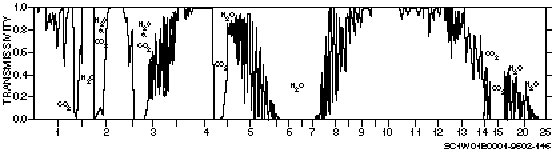
Figure 3–11. Major absorption bands of atmospheric gases in the region
from 0.5m m to 25m m.
Low transmittance values indicate strong absorption. Note the existence of little or no absorption in the region from 3.5 to 4.2m m and the region from 8.5 to 13m m. These two regions are the so-called atmospheric windows. Fortunately, the second window occurs in the range where Wien’s law tells us that the peaks of interest for most targets and backgrounds should occur. If the absolute humidity (the total mass of water vapor molecules in a volume of air, measured by dew point) is high, water vapor absorption becomes significant; it partially "closes" the window to the IR sensor. The term b aer abs depends on relative humidity and the aerosol type. When the relative humidity is greater than roughly 90 percent, significantly large haze forms that can significantly degrade IR contrast transmission. The type of aerosol determines the growth rate of haze. As for visual systems, the term b precip is responsible for the greatest degree of contrast degradation. In this case, extinction is due to absorption by precipitation droplets rather than by scattering.
Beer’s law
To understand the relationship between distance and visibility, consider this simple example. Assume that 100 photons are emitted or reflected by a target in the direction of the sensor. Now assume that a certain percentage of photons is scattered or absorbed in each kilometer of the atmosphere that the photons travel through. For example, if this percentage is 10 percent, then at 1km only 90 photons are left. At 2km, 81 remain (90 percent of 90). At 3km, we have 73 photons and at 4km there remain only 66. What we just described is an exponential decrease of energy with distance from the target scene. This relationship is known as Beer’s law, and is expressed mathematically as:
![]()
where b Tot , the total extinction coefficient, is expressed as the sum of individual extinction coefficients for molecular scattering, molecular absorption, aerosol scattering, aerosol absorption, and precipitation (e is a constant equal to approximately 2.718):
![]()
This relationship applies to both visible and IR wavelengths, but not all the five terms are always significant. In this expression, the factor e-b x represents the transmissivity.
Contrast may be either visible or IR contrast. In the example (fig. 3–12), the inherent contrast, 10, occurs at a distance of 0km. At 4km, the apparent contrast is 4, so the transmissivity at 4km is 0.4 or 40 percent (4/10). An arbitrary value of 2 has been set for the threshold contrast. At just over 7km, the apparent contrast is equal to the threshold contrast. This is the maximum possible lock-on or acquisition range; beyond this, there is not enough apparent contrast to make the sensor active. To find apparent contrast, just go some distance along the horizontal axis and then read the corresponding value for contrast along the vertical axis. Threshold contrast is shown as a horizontal line that intersects the vertical axis at the threshold contrast value. Where this line crosses the exponential curve gives the maximum lock-on or acquisition range (depending on the type of sensor). Beyond this point, lock-on or acquisition is impossible.
Figure 3–12. An example of Beer’s law.
Beer’s law accounts for the amount of image light (signal) that is scattered or absorbed between the target scene and the sensor. This light is lost from the path. There is a second way that visible contrast is degraded. If nonimage light (noise), such as sunlight, shines on the path, this light may be scattered into the sensor. Any type of scattering may cause sunlight to be scattered into the path between the object and the sensor. The light that is scattered into the sensor is called airlight or path radiance. A familiar example of airlight is the blueness of objects, such as mountains, in the distance. The farther away the mountains are, the bluer they appear. This type of airlight is the result of Rayleigh scattering, hence the blue color.
The whiteness of haze is also due to airlight. Sunlight gets (Mie) scattered from haze particle to haze particle until it is eventually scattered into your eye. Airlight can be as significant a cause of contrast degradation as extinction. The degree of contrast degradation depends on the distance between the target and sensor.
032. Reflected energy systems (other than visual)
Laser systems
Laser systems cannot be used without a CFLOS. The wavelength of tactical lasers is 1.06m m, which, in the NIR, is very close to the visible spectrum. Not surprisingly, lasers are subject to the same types of scattering that impair visible systems. Besides these, there are refractive effects that can seriously degrade beam propagation.
The first of these is beam scintillation. This is caused by microscale turbulent eddies much smaller than the beam width. Scintillation causes fluctuations of energy intensity within the cross section of the beam, but does not bend the beam from a straight line of sight or alter the width of the beam.
The second refractive effect is beam spread. This occurs when the microscale eddies are smaller than, or about the same size as, beam width. Spread increases the cross-sectional area of the beam and decreases the intensity of its energy.
The third effect is beam wander. This is caused by microscale eddies larger than the beam width. Wander causes the beam to deviate from a straight line path and makes aiming more difficult. All three of these can occur simultaneously. The twinkling of stars is a result of these refractive effects.
Radar systems
Radar (millimeter/microwave) systems are mainly affected by precipitation and large convective cloud droplets. These systems operate at approximately the same wavelengths as weather radar.
033. Wavelength resolution-sensitivity relationships
There are two key relationships that describe the effectiveness of using a particular wavelength of EMR to image a target scene. As wavelength increases, resolution decreases. Longer wavelengths give poorer resolution than shorter wavelengths. As a forecaster, you are aware that the resolution of a geostationary IR satellite image is 7km, while the resolution of a visible image can be 1km. Millimeter/microwave sensors designed for imaging have the poorest resolution of all. On the other hand, as wavelength increases, weather sensitivity decreases. The resolution may not be as good, but using a longer wavelength allows pilots to operate under weather conditions that were formerly restrictive.
This text material discusses the basic physics of radiative transfer in the atmosphere, including contrast in both visible and infrared wavelengths, black-body theory, and electromagnetic energy propagation. Planck’s law gives the energy spectrum for a black body, the Stefan-Boltzmann law gives the total energy, and Wien’s law gives the wavelength of peak energy. Important relations between wavelength, resolution, and weather sensitivity are: (1) as wavelength increases, resolution decreases, and (2) as wavelength increases, weather sensitivity decreases.
The law of conservation of energy applies to a beam of radiation propagating between two points in the atmosphere. If we denote the origin as Point A and the receiver as Point B (see fig. 3–13), then the energy arriving at Point B is the sum of the energy transmitted to Point B and the energy reflected into the beam (path radiance) to Point B.
Figure 3–13. Components of EM radiation.
The two components of extinction are absorption and scattering. Scattering is more important in visible wavelengths while absorption is more important in IR. Extinction of IR is explained by the absorption terms in the extinction coefficient in Beer’s law. In visible wavelengths, extinction due to scattering is described by Beer’s law.
Airlight, or path radiance, is as important in visible contrast degradation as extinction. Visible contrast is defined as a difference in reflectivities or albedos, while IR contrast is defined as a difference in radiometric temperature. Contrasts are an important idea for understanding electro-optical systems. Figure 3–14 helps to describe the types of contrasts.
Figure 3–14. Type of contrast.
Self-Test Questions
After you complete these questions, you may check your answers at the end of the unit.
028. Electro-optical systems
1. Define a target acquisition system.
2. Define precision guided munition.
3. How do visual and far infrared imaging systems depend on contrast in a target scene?
029. Black-body radiation
1. Explain how EMR frequency is related to EMR wavelength.
3. Define Planck’s law.
4. Define the Stefan-Boltzmann law.
5. Define Wien’s law.
030. Contrast
1. What are the three types of contrasts and their definitions?
Figure 3–15. Lesson 030, self-test question 2.
3. Two aircraft, side by side, are approaching the same target with similar, but not identical, thermal imaging sensors. Aircraft A detects the target at 5.8nm, while aircraft B does not detect the target until it is 4.3nm away. What, then, can be said about the threshold contrasts of each aircraft?
4. What are the two fundamental types of reflection and their definitions?
5. On what does the rate of heating or cooling of the material that an object is made of depend?
031. Contrast transmission
1. Why is the sky blue?
2. Give an example of geometric scattering and how it occurs.
3. Illustrate how Beer’s law describes an exponential decrease of energy with distance from the target scene using 8 percent loss of photons per kilometer mile.
4. Using figure 3–15 and given a constant threshold contrast of 1.5° K, what is the maximum lock-on range for this electro-optical system?
032. Reflected energy systems (other than visual)
1. What are the refractive effects that can seriously degrade beam propagation? Explain the cause of each.
033. Wavelength resolution-sensitivity relationships
1. Explain the relationship between wavelength, resolution, and weather sensitivity.
Understanding the effects of the real-world weather on EO systems is based on the radiative transfer physics that we discussed earlier. We can now use this information to determine some of the effects of the atmosphere on the inherent and apparent contrasts of targets and backgrounds on the images acquired by visual and infrared sensors. With experience, we may develop rules of thumb that make our jobs as forecasters easier. These rules may be general and apply anywhere, or they may be specific to our location and our customer’s mission. It is up to you to develop the latter for your customer’s missions.
The weather parameters that drive the performance of electro-optical systems are sensitive to the wavelength. The table below illustrates the general relationships between the operational wavelength and the propagation medium. However, it is important to determine just which parameters have the most significant impact on the wavelengths of interest.
|
WAVELENGTH CATEGORIES |
VISIBLE 0.4m m –0.74m m |
NEAR IR 0.74m m –2m m |
MIDDLE IR 2m m –6m m |
FAR IR 6m m –15m m |
FAR-FAR IR 15m m –0.1mm |
MILLIMETER 0.1mm–1cm |
MICROWAVE 1cm–10cm |
|
RESOLUTION |
USUALLY DECREASES WITH LONGER WAVELENGTH |
||||||
|
WEATHER SENSITIVITY |
GENERALLY DECREASES WITH LONGER WAVELENGTH |
||||||
Inherent visible contrast
The environment affects inherent visible contrast chiefly by affecting the amount of illumination that a target receives. Illumination can be affected by a number of factors, including cloud cover, sun angle, and precipitation. Overcast clouds reduce the illumination of the target scene. Partly or mostly cloudy conditions can cause the illumination of the target scene to vary rapidly, depending on the amount of clouds present and their speed.
Sun angle has the most direct effect on illumination. It varies with the time of day, the day of the year, and the location (latitude and longitude) of the target. Two factors control the affect of sun angle. One is the angle of incidence as depicted in figure 3–16. The angle of incidence is measured between the ray of energy and a perpendicular at the point of incidence. The greater the angle of incidence, the less energy is received per square unit of area.
Figure 3–16. Angle of incidence.
The other factor is the depth of the atmosphere through which the sun’s energy travels, illustrated in figure 3–17. This is also a function of the angle of incidence and the latitude. The atmosphere is thicker near the equator, but as the angle of incidence increases, so does the effect of the slant-range path of the energy through the atmosphere.
Figure 3–17. The greater the angle of incidence, the more atmosphere
the energy travels through.
Fortunately, this environmental effect is 100 percent predictable. The sun always rises in the east and sets in the west, traveling through the south in the afternoon in the Northern Hemisphere north of the tropics. The sun rises north of east and sets north of west in the summer and rises south of east and sets south of west in the winter. Solar elevation angles are, therefore, much higher in the summertime than in the wintertime (for any given hour of the day) and are also greater as you go closer to the tropics.
Lunar angles are also easily computed on a small computer with a simple program. Sun and moon angles determine not only the amount of illumination received by a target, but also determine shadow length. Precipitation may also affect the inherent contrast by affecting the reflectivities of materials. Rain may cause changes in the reflectivities of painted surfaces, particularly by making dull or flat paints appear shinier. Rain may also cause the reflectivities of sands and soils to decrease, making them darker. Snow, if it is deep enough, can severely reduce contrast by covering the target and background or make dark objects stand out conspicuously if the ground is covered and the targets are not. Camouflage and smoke are deliberately used to reduce contrast as well as to break up regular patterns.
Apparent visible contrast
|
WEATHER PARAMETERS |
VISIBLE AND NEAR IR |
SHORT-WAVE IR |
MID-WAVE IR |
LONG-WAVE IR |
MILLIMETER MICROWAVE |
|
Low visibility |
Severe |
Moderate |
Low |
Low |
None |
|
Rain/snow |
Moderate |
Moderate |
Moderate |
Moderate |
Moderate/low |
|
High humidity |
Low |
Low |
Moderate |
Moderate |
Low/none |
|
Fog/cloud |
Severe |
Severe |
Moderate/ severe |
Moderate/ severe |
Moderate/low |
|
Fog/oil/smoke |
Severe |
Moderate |
Low |
Low |
None |
|
Phosphorus/ dust |
Severe |
Moderate/ severe |
Moderate |
Moderate |
Low/none |
Weather conditions affect contrast transmission more than they do inherent contrast. If clouds are present in any amount between the target and sensor, they block the view entirely. Visual systems, therefore, require a CFLOS. As indicated in the table above, the natural visibility restrictions, such as fog, haze, precipitation, and dust, degrade target acquisition and lock-on directly by reducing visibility. The single most important parameter in determining lock-on and acquisition ranges is visibility. In the battlefield environment, there are restrictions to visibility besides those that occur naturally. Obscurants such as smoke may be used to deliberately shield moving targets from sight. Battlefield-induced contaminants (BIC) such as smoke from burning targets and dust raised by bomb impacts also obscure the target scene. These conditions may change rapidly and be difficult to forecast accurately, even with the most current intelligence information.
It is easy to understand the types of effects that visibility restrictions have on target acquisition—after all, your eyes are EO sensors that operate in the visible portion of the spectrum.
Inherent thermal contrast
There are many more environmental effects on inherent thermal contrast than there are on inherent visible contrast. Vehicular IR targets are self-heated; they supply their own EMR. The operating condition of the target (i.e., whether it is off, idling, or exercised) has a great effect on the amount of energy it emits and, therefore, the contrast. If the target is heated only by the sun (passively heated) or other natural sources of energy, its contrast with the background depends on the differences in the absorptivity, thermal conductivity, and thermal capacity of the target and background. Self-heated targets also receive passive heating; both must be taken into account to determine their temperatures.
Precipitation
Rain and snow equalize the temperatures of passively heated objects and their backgrounds and reduce thermal contrast. As the precipitation covers the targets and backgrounds, conduction between target and background materials and the precipitation causes all temperatures to become approximately the same. Self-heated targets, however, stand out against homogeneous backgrounds. Conductive heat transfer is not the only effect that precipitation has, however. The uneven evaporation (and evaporative cooling) of rain and the melting of snow can cause an increase in thermal complexity (number of objects that may be mistaken for target). The more mottled a target scene is, the closer an aircraft must get to sort out targets and backgrounds. The concept of scene complexity is demonstrated in figure 3–18.
Figure 3–18. Scene complexity.
Recent precipitation is as important as present precipitation in determining thermal contrast. It can obliterate the thermal contrast of passively heated targets and backgrounds and enhance the contrast for self-heated targets. The thermal responses of objects determine how quickly thermal contrast is restored once the precipitation ends. For this reason, be sure to consider the recent weather in the target area when you prepare an EO forecast rather than just the forecast conditions for the time-on-target (TOT).
Clouds
Clouds reduce insolation to passively heated objects and, therefore, reduce the thermal contrast between passively heated targets and backgrounds. Backgrounds appear more homogeneous (less complex) but passively heated targets blend in with them. As with precipitation, self-heated targets appear warm against a homogeneous background. Clouds also reduce the net amount of radiative cooling of targets and backgrounds at night, thereby reducing the thermal contrast of passively heated objects. The temperatures of exercised self-heated targets are fairly uniform throughout the day, so these appear warm against cooler backgrounds at night. Thicker low and middle clouds reduce thermal contrast more than thinner high clouds. Also, the greater the extent of the cloud, the lesser the insolation and radiative cooling will be. Scattered clouds have very little effect, while the effect of broken or overcast clouds may be quite significant.
Wind
Wind increases the amount of heat lost from all objects and reduces contrast for all target scenes. In other words, the greater the wind speed is, the less the thermal differences between targets and backgrounds will be. The degree to which wind cools a target varies the most for low wind speeds, generally less than 10 knots. It is therefore critical to forecast wind speed with the highest possible degree of accuracy when wind speeds are low. An 8-knot wind cools a target much more than a 4-knot wind, but a 50-knot wind speed does not have much more effect than a 20-knot wind. Although the effect is not as pronounced at generally higher wind speeds, getting the wind speed forecast correct is essential.
Crossover
Passively heated objects heat up and cool off at different rates and by different amounts over the course of the day. An object with a rapid thermal response is warmer than an object with slow thermal response in the late morning and afternoon. It is also cooler than an object with slow thermal response in the predawn hours. If a target is warmer than its background during the day and cooler than its background at night, then there must be two times during the day when their temperatures are the same, as shown in figure 3–19. The temperature of the passively heated target is represented by the dashed curve. These times are called crossover times and occur just after dawn and usually near sunset. These are the worst times of the day for using IR systems. For exercised self-heated targets, crossover occurs only on very hot days on certain backgrounds, such as desert sands and asphalt roads. On very hot days, these backgrounds may heat up to the same temperature as the self-heated target and make IR systems difficult to use. In this situation, crossover may occur only in the afternoon when target and background temperatures are the same. Targets and backgrounds may stay "crossed-over" for the entire afternoon.
Figure 3–19. Thermal crossover.
Thermal crossover is a function of viewing direction. For example, consider a tank that has not been exercised for several days. The top graph in figure 3–20 shows the daytime temperature curve for each side of the tank and the grass background. The bottom graph shows the temperature difference between each side and the background. As you can see, whether a target is hotter or colder than the background depends on both the time of day and the viewing angle.
Apparent thermal contrast
Thermal contrast transmission is affected mostly by the presence of water in the air, either in vapor or droplet form. The most severe restrictions on contrast transmission are due to precipitation. Rain, snow, and other forms of precipitation cause severe attenuation of target/background contrast transmission due to absorption by droplets. Similarly, clouds severely attenuate contrast transmission. High absolute humidities (high dew points) restrict thermal contrast transmission by water vapor absorption. Lithometeors, such as dust and haze, have little effect in dry air; however, when the relative humidity increases to about 90 percent or higher, significantly large haze droplets can form that impair apparent contrast to the same extent as fog and rain droplets.
Figure 3–20. Thermal crossover of a tank against a grassy background.
Prevailing meteorological conditions, like those shown in figure 3–21, can have significant effects on how objects appear to an EO sensor. These effects may be detrimental or beneficial. It is therefore critical that you not only accurately forecast parameters, but that you know which affect the type of sensor that you are preparing your forecast for and which do not. Always concentrate your forecasting effort on those factors that have the greatest effect. Weather affects not only contrast transmission, but inherent contrast as well. Threshold contrast is unaffected by the weather conditions, except for ablation. Ablation is atmospheric deterioration of the lens surface of a weapon’s sensors.
Figure 3–21. Weather that affects electro-optical systems.
Self-Test Questions
After you complete these questions, you may check your answers at the end of the unit.
034. Visual systems
1. What are the two factors that control the effect of the sun’s angle on illumination?
2. Explain some of the restrictions to visibility in a battlefield environment and how they can be accurately forecasted?
035. Infrared systems
1. If a target is heated only by the sun, on what does its background contrast depend?
2. Explain how precipitation affects the temperature of passively heated objects and their backgrounds and of self-heated targets.
3. How does wind affect a target scene?
5. What are the causes of the most severe restrictions on contrast transmission and how?
When a smart weapon system is designed, the first question answered is, "What role will the system perform on the battlefield? This role is to support the doctrine of the US Air Force and US Marine Corps for air-to-ground missions. In order to assess the impact of weather on the EO systems, it is necessary to understand the contribution that the EO system gives to the mission. This section briefly presents these concepts to provide a basis for greater understanding to be gained through working with the pilots that fly the missions.
Before we discuss some of the high-tech equipment available for aircrews to acquire and engage targets, we should discuss how a pilot or aviator acquires a target. Actually, the steps we describe apply to any situation in which someone is acquiring an object, whether it is a pilot or an aviator attacking an enemy communications facility or you looking for a parking space at the airport. Let’s consider the latter example, then we’ll see that the steps that aircrews go through are quite similar.
The first thing that you must do when you get to the airport is find the parking garage. Once you’ve done that your work really begins—finding an empty space. After a few minutes, you’ve acquired your target—you’ve found a spot. Now you have to determine your approach. Is it straight in or angle parking? Do you have to parallel park? Once you determine the orientation of the space, you have to make sure that it is okay to park there. Is the space reserved or marked with a handicapped sign? If it’s okay to park there, then the last thing you might do before you turn off the engine is to note exactly where you parked; that is, which floor, section, and space number. Without realizing it, you have just executed the classic target acquisition cycle, or CTAC.
036. The classic target acquisition cycle (CTAC)
CTAC is a five-step process that aircrews use to acquire and destroy targets. It includes the following phases: target area detection (finding the garage), target detection (finding a parking space), target orientation (angled, straight-in, or parallel), target recognition (reserved or handicapped parking), and target identification (floor, section, space). Now let’s consider each phase of the CTAC (depicted in fig. 3–22) as it applies to tactical situations.
Figure 3–22. Illustration of the classic target acquisition cycle (CTAC).
Phase I—target area detection
There are many resources available to help the pilot or aviator detect the target area. Before the mission, they may have access to photographic intelligence. They may be in contact with forward air controllers (FAC) or tactical air control parties (TACP) on the ground or with airborne FACs in aircraft such as the OA–10A Thunderbolt II or OV–10D Bronco. Aircrews might also be in contact with airborne command, control, and communications (ABCCC) EC–130 aircraft for taskings.
Besides FACs and ABCCC, pilots assigned to attack specific hardened targets have their route of flight planned to the last detail. To make sure they adhere to the plan, they may use many navigation aids. These may include some of the target acquisition systems we discuss, terrain following radar, and inertial navigation.
The latest development in providing support to the air-to-ground mission is the E–8A JSTARS (Joint Surveillance Target Attack Radar System). This is a modified EC–135 with a sideways looking radar that provides up-to-date information on ground targets directly to aircrews. It is the air-to-ground equivalent of the E–3A Airborne Warning and Control System (AWACS).
Phase II—target detection
Once the pilot or aviator enters the target area, that individual must find either a specific target or a suitable target of opportunity, depending on a number of factors. The first of these is the target-to-background contrast, which can be a thermal or visual brightness contrast. This is something that you will be able to forecast. The second factor is the size of the target. Obviously, bigger targets are easier to find than smaller targets. The next factor is the size of the target area that the pilot must scan. If the battle area is extensive, a pilot must spend more time finding a suitable target. The amount of time available to scan the target area also affects the pilot’s success in detecting the target. Another factor is the motion of the target, moving targets being easier to detect.
A successful attack depends on more than just dropping a bomb or firing a missile. It depends on coordination, skillful maneuvering, avoidance of air defenses, and communication. The degree of task saturation is, therefore, also a major factor in target detection. Sensor sensitivity, whether it is a sophisticated piece of EO equipment or the human eye, also affects target detection.
Finally, we must consider the existing weather. Precipitation and other obstructions to visibility make it more difficult to acquire targets. All these factors are critical for mission success. Some of them, such as contrast and existing weather, are predictable and some are not. Even with the most accurate tactical decision aid, if the pilot is not looking in the right direction, the target will not be hit.
Phase III—target orientation and pattern recognition
After the pilot or aviator finds the target, that individual must then recognize potential targets and determine their orientation. Determining the orientation of a high value or hardened target is fairly easy. With clear intelligence photos, the aircrew has some idea of what the target looks like before they get to the area. Fixed and hardened targets are regularly shaped and stand out against backgrounds of natural objects like hills and trees. Given the exact location of these fixed targets, the aircrew knows exactly where to look as they approach the area. Vehicular targets are more challenging because their orientations and operating states change frequently. Their movement may reveal orientations as well as their locations.
Phase IV—target recognition
After the pilot determines the orientation of the target, that person can classify the type of target. For example, instead of identifying a potential target as either a building or a vehicle, the pilot is able to determine that it is a hardened aircraft shelter or a tank.
Phase V—target identification
The final stage of the CTAC is to determine the specific target. By this stage, the pilot can determine that the specific target that is about to be attacked is a specific hardened aircraft shelter (e.g., the third one on the left on taxiway D) or a specific type of tank (e.g., a T–80). The pilot can distinguish friend from foe.
The CTAC may occur within seconds and phases may occur simultaneously. If the pilot adheres to all five phases, that individual may then bring back valuable bomb damage assessment information that makes future taskings more effective.
Aircrews receive their taskings (or "frags") via a document known as an air tasking order (ATO). The ATO is prepared daily at the tactical air control center (TACC) and is issued for all sorties flown in the theater of operations. The ATO specifies the target, time on target (TOT), and weapons load for each aircraft.
According to US Air Force doctrine, the three fundamental functions of tactical air power are close air support, air superiority, and air interdiction. In US Marine Corps doctrine, six functions of aviation are defined, two of which include the three primary functions of tactical air power as defined by the Air Force. Offensive antiair warfare (OAAW) is equivalent to air superiority, while offensive air support (OAS) includes both air interdiction and close air support missions (as well as armed reconnaissance). These are doctrinal distinctions; specific types of missions and their ultimate objectives are essentially the same for all three branches and are based on the target. Tactical decision aids may be required for any of these types of missions. To provide the best possible support to your customer, it is important to understand the types of missions that your customer is tasked to perform in wartime and for which they train in peacetime. Some of these different types of air-to-surface missions include: close air support, air interdiction, suppression of enemy air defenses, and offensive counter air.
Close air support (CAS)
CAS is support of friendly ground forces in close proximity to, or engaged with, enemy forces along the forward edge of the battle area (FEBA). In a CAS mission, the pilot must adhere to CTAC before releasing weapons. Typical targets include vehicles and personnel. CAS missions are typically flown by the A–10 Warthog, F–16 Fighting Falcon, F/A–18 Hornet, AV–8B Harrier II, and AH–64 Apache. CAS missions may be planned or flown on an alert basis.
Besides CAS, the Marine Corps doctrine describes close-in fire support (CIFS). CIFS is unique to attack helicopters such as the AH–1W SuperCobra. CAS/CIFS is one of the two major categories of OAS.
Air interdiction (AI)
AI strikes are against enemy targets far behind the FEBA or the forward line of own troops (FLOT). In an AI mission, a pilot may only have to adhere to Phases I– IV of the CTAC if target recognition is essential and only if nothing else in the area is protected by the law of armed conflict (LOAC). These protected elements include, but are not limited to, hospitals, civilian residential areas, hotels, or religious and cultural structures, such as churches, mosques, temples, or shrines. The pilot may also have to adhere to all five phases of the CTAC if the munition must hit a specific building or section of building. AI missions may be flown by the F/A–18 and A–6E Intruder, F–117 (stealth), F–15E Strike Eagle, F–16, and F–111F.
Interdiction of lines of supply and communication to the FEBA and strikes against enemy troops that are about to be engaged is called battlefield air interdiction or BAI. In the Marine Corps doctrine, AI is one type of deep-air support, which is the other major category of OAS.
Suppression of enemy air defenses (SEAD)
SEAD missions are strikes against air defenses, including antiaircraft artillery (AAA), surface-to-air missile (SAM) batteries, and ground control intercept (GCI) radar. In many SEAD missions, antiradiation missiles may be employed by F–4G Wild Weasels and EA–6B Prowlers. The CTAC is not necessarily adhered to as the target is identified when enemy radar is activated. Alternatively, more conventional munitions or other types of PGMs may be employed. SEAD is a category of OAAW.
Offensive counter air (OCA)
OCA missions are strikes against enemy airfields, including aircraft on the ground, hardened shelters, and control and support facilities. Adherence to the CTAC is not necessary for this type of mission. OCA strikes are flown by F–111Fs, F–15Es, and F/A–18s. In the Marine Corps and Navy doctrine, these types of missions are generally referred to as Strike missions, or as "preemptive measures" under OAAW.
To launch a bomb or missile safely and effectively, aircrews must consider the launch envelopes of their weapons. The launch envelope is merely the range of altitudes and distances within which the weapon can effectively reach the target without exposing the aircraft to enemy air defenses. The inner edge is determined by the range of enemy air defenses. Obviously, you want to stay out of their range. The upper edge is determined by cloud base, which determines not only the ceiling of the aircraft, but also the altitude to which a bomb or missile may be lofted or tossed. The outer edge is determined by the lesser of the range of munition or the visibility, lock-on range, or detection range of the weapon itself. The aircraft must be close enough to detect, or lock on to, the target and within the range of the weapon. These components of the launch envelope are shown in figure 3–23.
Figure 3–23. The launch envelope and safe launch zone.
Self-Test Questions
After you complete these questions, you may check your answers at the end of the unit.
036. The classic target acquisition cycle (CTAC)
1. What are the five phases of CTAC?
Column A _____ 1. The first factor to consider is the target-to-background contrast. _____ 2. During this phase, the pilot can distinguish friend from foe. _____ 3. Aircrews are in contact with Airborne Command, Control, and Communications (ABCCC) EC–130 aircraft for their taskings. _____ 4. During this phase, the size of the target area that must be scanned is a factor. _____ 5. After the pilot or aviator has found the target, that individual must then recognize potential targets and determine their orientation. _____ 6. After the pilot determines the orientation of the target, that person classifies the type of target. _____ 7. The aviators may use many navigation aids to make sure they adhere to the plan. |
Column B a. Target detection. b. Target identification. c. Target recognition. d. Target area detection. e. Target orientation and pattern recognition. |
037. Air-to-ground missions
1. List and describe the four types of Air Force air-to-ground missions.
038. Launch envelope
1. Define and describe the limits of the launch envelope.
Precision-guided munitions are missiles, bombs, or artillery shells that are equipped with a terminal guidance system. They may be categorized according to their guidance sensor types as in figure 3–24. This section deals with the electro-optical and radar guidance types because environmental support is more critical for them than for inertial guidance systems. While radar guidance systems are much less sensitive to environmental degradation than electro-optical systems, it is still necessary to know how they function to support the air-to-ground missions. This fact was emphasized by Admiral Thomas Moorer when he stated:
One of the most difficult decisions facing the operational commander today is the selection of the optimum weapon systems to be used—such a decision cannot be made without competent weather advice.
Figure 3–24. Munition guidance types.
All precision-guided munitions include certain components. They all have an explosive payload that can vary from the relatively small 18 pound (lb) shaped-charge of the air-to-ground (AGM)–114 Hellfire missile to the 4,700 lbs of high explosives of the GBU–28 laser-guided bomb. The bomb or missile uses planar or cruciform wings or fins, like those shown in figure 3–25, that allow for changes in course or direction after release. Notice the planar wing in the lower right corner. It is like an aircraft’s wing and increases the range of a munition that is released at high altitudes. The more common cruciform wing is mounted close to the tail and (or) mid-section of the munition, or may extend the entire length of the munition. The fins are at 90 degree angles. They do not extend range, but control the direction of the glide bomb or missile.
Figure 3–25. GBU–15 components.
A missile has some means of propulsion, which is either a solid fuel rocket motor (found on air-to-ground missiles) or a jet turbine engine (found on cruise missiles). Rocket motors and turbine engines significantly increase the range of the munition. All PGMs, whether glide bombs or missiles, require some form of guidance system.
039. Three types of PGM systems
Figure 3–26 shows the three types of PGM systems that we discuss: active, passive and semi-active.
Figure 3–26. Types of PGM systems.
Active
An active guidance system provides the energy for target illumination and detects this energy as it is reflected by the target. An active system has the designator and sensor in the same unit. Active systems are generally radar systems. Because of the high cost of putting a complete radar set on a missile that is to be used only once, active PGMs are only used against high-value targets such as ships.
Passive
A passive guidance system detects energy that originates from the target itself. A passive TV-guided bomb or missile has an imaging system that detects contrasts in reflected sunlight between the target and the background (or detects the light of the target itself). A passive IR guided bomb or missile has an imaging system that detects contrasts in the emitted far infrared energy between the target and the background. A third type of passive system, the antiradiation missile, detects the radar energy emitted from enemy air defense weapons.
Semi-active
A semi-active guidance system is a sensor that detects reflected energy provided by a designator that is not on the munition. This designator may be on the same aircraft, on a different aircraft, or on the ground (but not on the munition). Semi-active systems include radar and laser systems.
PGMs may be used in a variety of employment modes. Each mode is determined by the sequence in which the weapon is released (launched), the system locks on to the target, and the aircraft leaves the target area.
The lock-on/launch/leave (LO/LA/LV), or direct attack mode, may be used with any PGM. It must be used with weapon systems for which there is no communication or telemetry or data link between the munition and the aircraft after the weapon is released. This mode is compatible with passive, active, or semi-active systems.
The launch/lock-on/leave (LA/LO/LV) may be used with passive systems equipped with telemetry apparatus as in figure 3–27. It is also used for laser-guided munitions if the aircraft that launched the weapon designates the target. Because the target must be designated up to impact, the pilot may not exit the area until the bomb hits the target.
The launch/leave/lock-on (LA/LV/LO) may be used with passive systems equipped with telemetry and active and semi-active systems. This mode may be used with laser-guided bombs if another aircraft or ground-based laser designates the target (buddy designating). The pilot may exit the area immediately after weapons release if designation of the target is not required. This mode of employment is often referred to as "fire-and-forget."
Figure 3–27. Passive system equipped with telemetry.
041. Employment tactics for PGMs
The pilot, aircraft, and target acquisition system exist to put the munition on the target. The tactics used to deliver the weapon determine how effectively the munition damages the target. The types of tactics employed depends on a number of factors: the angle the bomb must strike the target to do the most damage, the distance from the target for a safe egress, and the type of munition itself. This text material briefly describes the laydown, the high and low angle dive, the toss, the loft, and the orbit bombing tactics. The sneak and peek tactic for use with missiles is also described. Pay particular attention to the factors affecting the effectiveness of these various tactics.
A laydown, figure 3–28, is the release of artificially retarded weapons by aircraft passing over the target at low altitude. This tactic is generally not used for precision-guided munitions, but for cluster bombs and runway cratering munitions.
Figure 3–28. Laydown weapons delivery tactic.
In a high altitude dive bomb weapon delivery, as shown on the left of figure 3–29, the aircraft approaches the target area at either low, medium, or high altitude. Near the target, the aircraft either remains at middle or high altitude or pops up to a sufficient altitude for weapon delivery. When the aircraft is just about over the target, it initiates a high angle dive, usually between 60 and 80 degrees. The aircraft releases the weapon and then egresses the target area.
There are several advantages to this type of delivery. It is easier to sight the weapon because the gravity vector is nearly parallel to the flight path. The bomb’s trajectory does not deviate from the sight path, so smaller sighting corrections are needed. The increased kinetic energy (high velocity) is useful for penetration of hardened targets and decreases the chance of ricochet. High altitude dive bombing may be the only option for certain mountainous terrain. It is also easier to view down through the haze layer from a high angle.
There are several disadvantages, however. There is an increased exposure to enemy air defenses. With delivery from higher altitudes, there is a greater variation in the winds along the bomb’s flight path and higher ceilings are required.
Figure 3–29. High and shallow angle dive bombing tactic.
In a shallow angle dive bomb, as shown on the right of figure 3–29, the aircraft approaches the target at low or middle altitude. At a predetermined distance from target, the aircraft initiates a low constant angle approach (1 to 20° ), maintaining 1 gravity (g). The aircraft releases the weapon and then egresses the target area.
The principle advantage is that the aircraft spends a minimum amount of time away from a very low-level flight profile. This tactic is useful for missile attacks against armor and strafing (guns and missile salvos). This tactic allows for lower ceilings than high angle dive bombing and toss/loft tactics.
The principle disadvantage is the susceptibility to all air defenses from SAMs to small arms. This tactic also requires higher visibilities.
Both the toss and the loft tactics begin with a low altitude approach to target with a pop up at a predetermined point, usually about 5nm from the target. In a toss, the aircraft and bomb are pulling more than 1g because the bomb is released by the aircraft on the climbing portion of loop as shown in figure 3–30. In a loft, the aircraft is pulling only 1g because the bomb is released by the aircraft in a straight angled climb as shown in figure 3–31. After the bomb is released, the aircraft may egress the target area.
Figure 3–30. Toss bombing tactic.
Figure 3–31. Loft bombing tactic.
There are several advantages to these tactics. Most importantly, the aircraft has increased stand-off range from enemy air defenses than with high altitude dive bombing. Because the bombs are released from a relatively low altitude, there is less of a problem with winds (although winds are still an important consideration). This tactic can also be used with lower ceilings; however, ceilings must still be greater than the altitude to which the bomb is lofted or tossed (g-biased). With these tactics, terrain masking can be used effectively for self-defense.
The disadvantages include more difficult sighting of the bomb because the gravity vector is at a much greater angle to the sight path (almost 90° ), so more correction is required. Greater visibilities are also required. This technique also results in shallower impact angles, so there is a greater chance of a ricochet.
Aircraft may orbit the target area at a safe stand-off distance (5 to 10km) and drop their bombs from a high altitude and then remain at the stand-off distance to guide the weapon. This tactic is particularly useful for multiple aircraft working off a single aircraft’s laser designator as in figure 3–32. Like the high angle dive bomb, bombing trajectory calculations are straightforward and haze is less of a problem than for other tactics.
Figure 3–32. Orbit or wheel bombing tactic.
This method is used only by helicopters. The helicopter hovers behind foliage, as in figure 3–33, and comes up only for target acquisition or attack. The main advantages are protection from air defenses and small arms fire. The main disadvantage is that it only works in forested areas or areas with sufficient foliage or other natural obstructions. It is difficult to employ in desert environments.
Figure 3–33. Sneak and peek tactic.
Self-Test Questions
After you complete these questions, you may check your answers at the end of the unit.
039. Three types of PGM systems
1. List and describe each of the types of PGM systems.
040. Employment modes
1. Explain how each of the various employment modes of a PGM is determined.
041. Employment tactics for PGMs
1. On what do the different types of PGM employment tactics depend?
2. List the different types of PGM employment tactics.
3. Match each weapons delivery tactic or tactics in Column B with its advantage or disadvantage of the tactic in Column A. Items in column B may be used once, more than once, or not at all. Each question may have more than one answer.
Column A _____ 1. Less affected by haze. _____ 2. Minimizes time spent away from level flight. _____ 3. Minimizes chance of ricochet. _____ 4. Force multiplier for target acquisition system (multiple aircraft per target acquisition system). _____ 5. Increases stand-off range. _____ 6. Significantly affected by haze. _____ 7. Not available to fixed-wing aircraft. _____ 8. Effective for aerodynamically retarded munitions. |
Column B a. Orbit. b. Laydown. c. Enfilade. d. Toss/Loft. e. Cut and run. f. Sneak and peek. g. High angle dive bomb. h. Shallow angle dive bomb. |
Answers to Self-Test Questions
028
1. It’s an electro-optical sensor that is mounted on an aircraft.
2. It’s when an electro-optical sensor is mounted on a bomb or missile.
3. Visual systems depend on the contrast between the reflectivities of objects in a target scene, while FIR imaging systems depend on the contrast between the emitted thermal energy of the different objects in a target scene.
029
1. The frequency (n
) of waves is inversely proportional to the wavelength based on the following formula: (n
=![]() ). For example, EMR with a short wavelength has a high frequency and vice versa.
). For example, EMR with a short wavelength has a high frequency and vice versa.
2. Radiated (emitted) and reflected energy.
3. This law illustrates the amount of energy emitted by a black body at a specific temperature for each wavelength of the electromagnetic spectrum.
4. This law describes the total amount of energy emitted at all wavelengths of the electromagnetic spectrum to the temperature of a black body
5. Wien’s law describes how the wavelength of most of the energy emitted by an object is inversely proportional to its temperature?
030
1. They are inherent contrast, apparent contrast, and threshold contrast. Inherent contrast is the actual contrast between two objects based solely on their properties. Apparent contrast is the contrast that a person or an EO sensor detects at some particular distance from a target scene. Threshold contrast is the smallest contrast that can be detected by a sensor or by the human eye.
2. 5° Kelvin.
3. The threshold contrast for aircraft A is greater than the threshold contrast for aircraft B.
4. These are perfect, or specular, and diffuse reflector. The perfect reflector has the angle of incidence equaling the angle of reflection. With a diffuse reflector, light is reflected in all directions equally, but the energy is diffuse.
5. The absorptivity of the material, the thermal conductivity, and the thermal capacity.
031
1. Because Rayleigh scattering depends on wavelength. Shorter wavelengths, such as blues, are scattered more than longer wavelengths, such as reds. The blue photons that are coming from the sun are scattered more times than the red photons; therefore, they are more widely distributed across the sky.
2. The effect that occurs when you use your high beams on foggy nights. Geometric scattering occurs when most of light is scattered in a backward direction by the fog droplets.
3. At 1km only 92 photons are left, at 2km, 85 photons remain, at 3km, 78 photons remain, and at 4km only 66 photons remain.
4. 5.1 kilometers.
032
1. Beam scintillation, beam spread, and beam wander. Scintillation is caused by microscale turbulent eddies that are much smaller than the beam width causing fluctuations of energy intensity within the cross section of the beam. The beam does not bend from a straight line of sight or alter the width of the beam. Beam spread transpires when the microscale eddies are smaller than or about the same size as beam width. The spread increases the cross-sectional area of the beam and decreases its energy intensity. Wander is caused by microscale eddies larger than the beam width causing the beam to deviate from a straight line path making aiming more difficult.
033
1. As a wavelength increases, its resolution decreases, and its weather sensitivity decreases.
034
1. The angle of incidence and the depth of the atmosphere through which the sun’s energy travels.
2. In a battlefield situation/environment, there are natural restrictions to visibility such as fog, haze, etc. and those that do not occur naturally. Smoke may be used to deliberately shield moving targets from sight during a battle. Battlefield-induced contaminants (BIC), such as the smoke from burning targets and dust raised by bomb impacts, also can obscure the target scene. Because these conditions change rapidly and are mostly induced by man, they are at best difficult to forecast accurately even with the most current weather and intelligence information.
035
1. The differences in the absorptivity, thermal conductivity, and thermal capacity of the target and background.
2. As precipitation covers the passively heated targets and their backgrounds, conduction between the target and its background materials and the precipitation causes all the temperatures to become about the same. However, self-heated targets stand out against comparable backgrounds. Conduction and uneven evaporative cooling of rain and the melting of snow cause an increase in the thermal complexity of a target. Thereby the more mottling of a target scene the closer an aircraft must get to sort out the targets and the backgrounds.
4. At the two times during a day when a target and its background temperatures are the same (during the crossover times). This is due to the object being the same temperature as its background.
5. Rain, snow, and other forms of precipitation cause severe attenuation of the target/background contrast transmission due to the absorption by droplets. Clouds are very similar, they severely attenuate the contrast transmission. High dew points restrict the thermal contrast transmission by water vapor absorption, while lithometeors, such as dust and haze, have little effect in dry air. Still, when the relative humidity increases to ³ 90 percent, significantly large haze droplets can form that diminish apparent contrast to the same extent as fog and rain droplets.
036
1. Target area detection, target detection, target orientation, target recognition, and target identification.
2. (1) a.
(2) b.
(3) d.
(4) a.
(5) e.
(6) c.
(7) d.
037
1. Close air support (CAS), air interdiction (AI), suppression of enemy air defenses (SEAD), and offensive counter air (OCA). CAS is support of friendly ground forces in close proximity to or engaged with enemy forces along the forward edge of the battle area (FEBA). In a CAS mission, the pilot must adhere to CTAC before releasing weapons. CAS missions may be planned or flown on an alert basis. AI strikes are against enemy targets far behind FEBA or forward line of own troops (FLOT). In an AI mission, a pilot may only have to adhere to Phases I–IV of the CTAC, if target recognition is essential and only if nothing else in the area is protected by the law of armed conflict (LOAC). The pilot may also have to adhere to all five phases of the CTAC if munitions must hit a specific building or section of building. Interdiction of lines of supply and communication to the FEBA and strikes against enemy troops that are about to be engaged is called battlefield air interdiction or BAI. SEAD missions are strikes against air defenses, including antiaircraft artillery (AAA), surface-to-air missile (SAM) batteries, and ground control intercept (GCI) radar. The CTAC is not necessarily adhered to as the target is identified when enemy radar is activated. OCA missions are strikes against enemy airfields, including aircraft on the ground, hardened shelters, and control and support facilities. Adherence to the CTAC is not necessary for this type of mission.
038
1. The launch envelope is the range of altitudes and distances within which a weapon can effectively reach the target without exposing the aircraft to enemy air defenses. The range of the enemy air defenses determine the inner edge. The upper edge is determined by the cloud base; this determines the ceiling of the aircraft and also the altitude to which a bomb or missile may be lofted or tossed. The outer edge is determined by the lesser of the range of the munition or the visibility, the lock-on range, or the detection range of the weapon itself.
039
1. They are active, passive, and semi-active systems. An active guidance system provides the energy for target illumination and detects this energy as it is reflected by the target. A passive guidance system detects energy that originates from the target itself. A semi-active guidance system is a sensor that detects reflected energy provided by a designator not on the munition. This designator may be on the same aircraft, on a different aircraft, or on the ground but not on the munition.
040
1. Each mode is determined by the sequence in which the weapon is launched, the system locks on to the target, and the aircraft leaves the target area.
041
1. The types depend on: the angle the bomb must strike the target to do the most damage, the distance from the target for a safe passage, and the type of munition itself.
2. The laydown, the high and low angle dive, the toss, the loft, the orbit, and the sneak and peek tactics.
3. (1) a and g.
(2) h.
(3) g.
(4) a.
(5) d.
(6) d and h.
(7) f.
(8) b.
Unit Review Exercises
Note to Student: Consider all choices carefully, select the best answer to each question, and circle the corresponding letter. When you have completed all unit review exercises, transfer your answers to ECI Form 34, Field Scoring Answer Sheet.
Do not return your answer sheet to ECI.